- 您现在的位置:买卖IC网 > PDF目录1834 > LTC4110EUHF#TRPBF (Linear Technology)IC BATTERY BACKUP MANAGER 38-QFN PDF资料下载
参数资料
| 型号: | LTC4110EUHF#TRPBF |
| 厂商: | Linear Technology |
| 文件页数: | 6/52页 |
| 文件大小: | 0K |
| 描述: | IC BATTERY BACKUP MANAGER 38-QFN |
| 标准包装: | 2,500 |
| 功能: | 备份管理 |
| 电池化学: | 铅酸,锂离子,锂聚合物,镍镉,镍氢,超级电容器 |
| 电源电压: | 4.5 V ~ 19 V |
| 工作温度: | -40°C ~ 85°C |
| 安装类型: | 表面贴装 |
| 封装/外壳: | 38-WFQFN 裸露焊盘 |
| 供应商设备封装: | 38-QFN(5x7) |
| 包装: | 带卷 (TR) |
第1页第2页第3页第4页第5页当前第6页第7页第8页第9页第10页第11页第12页第13页第14页第15页第16页第17页第18页第19页第20页第21页第22页第23页第24页第25页第26页第27页第28页第29页第30页第31页第32页第33页第34页第35页第36页第37页第38页第39页第40页第41页第42页第43页第44页第45页第46页第47页第48页第49页第50页第51页第52页
�� �
�
�LTC4110�
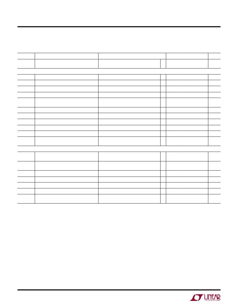
�ELECTRICAL� CHARACTERISTICS� The� l� denotes� the� speci?cations� which� apply� over� the� full� operating�
�temperature� range,� otherwise� speci?cations� are� at� T� A� =� 25°C.� Unless� otherwise� speci?ed,� V� DCIN� =� V� DCOUT� =� V� DCDIV� =� 12V,� V� BAT� =� 8.4V,�
�GND� =� SGND� =� CLP� =� CLN� =� SHDN� =� 0V� and� R� VREF� =� 49.9k.� All� currents� into� device� pins� are� positive� and� all� currents� out� of� device� pins�
�are� negative.� All� voltages� are� referenced� to� GND,� unless� otherwise� speci?ed.�
�SYMBOL�
�V� REMH�
�PARAMETER�
�THB� Pin� Battery� Removal� Threshold�
�CONDITIONS�
�V� THB� Decreasing;� Lead� Acid� Only�
�MIN�
�TYP�
�25�
�MAX�
�UNITS�
�mV�
�Hysteresis� Voltage�
�Logic� and� Status� Output� Levels�
�V� ILS�
�V� IHS�
�SCL/SDA� Input� Pins� Low� Voltage�
�SCL/SDA� Input� Pins� High� Voltage�
�l�
�l�
�2.1�
�0.8�
�V�
�V�
�V� OLS�
�V� OLG�
�SDA� Output� Pin� Low� Voltage�
�ACPb,� GPIO1,2,3� Output� Pins� Low� Voltage�
�I� PULL-UP� =� 350μA�
�I� ACPb� ,� I� GPIO1� ,� I� GPIO2� ,� I� GPIO3� =� 10mA�
�l�
�0.4�
�1�
�V�
�V�
�I� OHG�
�ACPb,� GPIO1,2,3� Output� Pins� Open�
�Leakage� Current�
�Outputs� Open,� V� ACPb� ,� V� GPIO1,2,3� =� 5V�
�–2�
�2�
�μA�
�V� ILG�
�V� IHG�
�V� ILSD�
�V� IHSD�
�GPIO� Input� Low� Voltage�
�GPIO� Input� High� Voltage�
�SHDN� Input� Pin� Low� Voltage�
�SHDN� Input� Pin� High� Voltage�
�l�
�l�
�1.5�
�2.4�
�1�
�0.5�
�V�
�V�
�V�
�V�
�I� ISD�
�T� LR�
�SHDN� Input� Pin� Pull-Up� Current�
�Logic� Reset� Duration� After� Power-Up�
�V� SHDN� =� 2.4V�
�V� DCIN� Transition� From� 0V� to� 5V� in� <1ms;�
�–3.5�
�–2�
�–1�
�1�
�μA�
�s�
�From� Zero�
�SMBus� Timing� (Note� 9)�
�V� BAT� =� 0�
�t� HIGH�
�SCL� Serial� Clock� High� Period�
�I� PULL-UP� =� 350μA,� C� LOAD� =� 250pF,�
�l�
�4�
�μs�
�R� PU� =� 9.31k�
�t� LOW�
�SCL� Serial� Clock� Low� Period�
�I� PULL-UP� =� 350μA,� C� LOAD� =� 250pF,�
�l�
�4.7�
�μs�
�R� PU� =� 9.31k�
�t� TO�
�Timeout� Period�
�l�
�25�
�ms�
�t� F�
�t� SU-STA�
�t� HD-STA�
�t� HD-DAT�
�SDA/SCL� Fall� Time�
�Start� Condition� Set-Up� Time�
�Start� Condition� Hold� Time�
�SDA� to� SCL� Falling-Edge� Hold� Time,�
�C� LOAD� =� 250pF,� R� PU� =� 9.31k�
�l�
�l�
�l�
�l�
�4.7�
�4�
�300�
�300�
�ns�
�μs�
�μs�
�ns�
�Slave� Clocking� in� Data�
�Note� 1:� Stresses� beyond� those� listed� under� Absolute� Maximum� Ratings�
�may� cause� permanent� damage� to� the� device.� Exposure� to� any� Absolute�
�Maximum� Rating� condition� for� extended� periods� may� affect� device�
�reliability� and� lifetime.� Speci?c� functionality� or� parametric� performance�
�of� the� device� beyond� the� limits� expressly� given� in� the� Electrical�
�Characteristics� table� is� not� implied� by� these� maximum� ratings.�
�Note� 2:� The� LTC4110E� is� guaranteed� to� meet� performance� speci?cations�
�from� 0°C� to� 85°C.� Speci?cations� over� the� –40°C� to� 85°C� operating�
�temperature� range� are� assured� by� design,� characterization� and� correlation�
�with� statistical� process� controls.�
�Note� 3:� This� IC� includes� overtemperature� protection� that� is� intended�
�to� protect� the� device� during� momentary� overload� conditions.�
�Overtemperature� protection� will� become� active� at� a� junction� temperature�
�greater� than� the� maximum� operating� junction� temperature.� Continuous�
�operation� above� the� speci?ed� maximum� operation� temperature� may� result�
�in� device� degradation� or� failure.� Operating� junction� temperature� T� J� (in�
�°C)� is� calculated� from� the� ambient� temperature� T� A� and� the� average� power�
�dissipation� P� D� (in� watts)� by� the� formula� T� J� =� T� A� +� θ� JA� ?� P� D� .�
�Note� 4:� The� LTC4110� is� idle� with� no� application� load.� It� is� not� charging�
�or� calibrating� the� battery� and� is� not� in� backup� or� shutdown� mode.� The�
�internal� clock� is� running� and� the� SMBus� is� functional.�
�Note� 5:� Combined� current� of� CSP,� CSN� and� BAT� pins� set� to� V� BAT� with� no�
�application� load.�
�Note� 6:� C� TH� is� de?ned� as� the� sum� of� capacitance� on� THA,� THB�
�SafetySignal.�
�Note� 7:� Does� not� include� tolerance� of� current� sense� or� current�
�programming� resistors.�
�Note� 8:� Given� as� a� per� cell� voltage� referred� to� the� BAT� pin� (V� BAT� /number� of�
�series� cells).�
�Note� 9:� Refer� to� System� Management� Bus� Speci?cation,� Revision� 1.1,�
�section� 2.1� for� Timing� Diagrams� and� section� 8.1,� for� t� LOW� and� t� TIMEOUT�
�requirements.�
�Note� 10:� Speci?cations� over� the� –5°C� to� 85°C� operating� ambient�
�temperature� range� are� assured� by� design,� characterization� and� correlation�
�with� statistical� process� controls.�
�4110fb�
�6�
�相关PDF资料 |
PDF描述 |
|---|---|
| LTC4150IMS#TRPBF | IC COUNTER/GAUGE GAS/BATT 10MSOP |
| LTC4155IUFD#TRPBF | IC I2C POWER MANAGER DUAL 28QFN |
| LTC4160EUDC-1#TRPBF | IC SWITCH POWER MANAGER 20-QFN |
| LTC4410ES6#TRPBF | IC POWER MANAGER USB TSOT23-6 |
| LTC4411ES5#TRMPBF | IC IDEAL DIODE LOW LOSS TSOT23-5 |
相关代理商/技术参数 |
参数描述 |
|---|---|
| LTC4120IUD#PBF | 制造商:Linear Technology 功能描述:BATTERY CHARGER, 400MA, QFN-16, Battery Type:Li-Ion, Li-Polymer, Input Voltage:4 |
| LTC4150 | 制造商:LINER 制造商全称:Linear Technology 功能描述:High Voltage, High-Side Current Sense |
| LTC4150_1 | 制造商:LINER 制造商全称:Linear Technology 功能描述:Coulomb Counter/ Battery Gas Gauge |
| LTC4150CMS | 功能描述:IC COUNTER/GAUGE GAS/BATT 10MSOP RoHS:否 类别:集成电路 (IC) >> PMIC - 电池管理 系列:- 标准包装:61 系列:- 功能:电源管理 电池化学:锂离子(Li-Ion)、锂聚合物(Li-Pol) 电源电压:4.35 V ~ 5.5 V 工作温度:-40°C ~ 85°C 安装类型:表面贴装 封装/外壳:22-WFDFN 裸露焊盘 供应商设备封装:22-DFN(6x3)裸露焊盘 包装:管件 |
| LTC4150CMS#PBF | 功能描述:IC COUNTER/GAUGE GAS/BATT 10MSOP RoHS:是 类别:集成电路 (IC) >> PMIC - 电池管理 系列:- 其它有关文件:STC3100 View All Specifications 特色产品:STC3100 - Battery Monitor IC 标准包装:4,000 系列:- 功能:燃料,电量检测计/监控器 电池化学:锂离子(Li-Ion) 电源电压:2.7 V ~ 5.5 V 工作温度:-40°C ~ 85°C 安装类型:表面贴装 封装/外壳:8-TSSOP,8-MSOP(0.118",3.00mm 宽) 供应商设备封装:8-MiniSO 包装:带卷 (TR) 其它名称:497-10526-2 |
发布紧急采购,3分钟左右您将得到回复。