- 您现在的位置:买卖IC网 > PDF目录18777 > MAX1471ATJ+ (Maxim Integrated)IC RCVR ASK/FSK LP 32-TQFN PDF资料下载
参数资料
| 型号: | MAX1471ATJ+ |
| 厂商: | Maxim Integrated |
| 文件页数: | 11/26页 |
| 文件大小: | 0K |
| 描述: | IC RCVR ASK/FSK LP 32-TQFN |
| 其它有关文件: | Automotive Product Guide |
| 产品培训模块: | Lead (SnPb) Finish for COTS Obsolescence Mitigation Program |
| 标准包装: | 60 |
| 频率: | 315MHz,434MHz |
| 灵敏度: | -114dBm |
| 调制或协议: | ASK,FSK |
| 应用: | ISM,车库门开启器,RKE |
| 电流 - 接收: | 7mA |
| 数据接口: | PCB,表面贴装 |
| 天线连接器: | PCB,表面贴装 |
| 电源电压: | 3.3V,5V |
| 工作温度: | -40°C ~ 125°C |
| 封装/外壳: | 32-WFQFN 裸露焊盘 |
| 供应商设备封装: | 32-TQFN-EP(5x5) |
| 包装: | 管件 |
�� �
�
�315MHz/434MHz� Low-Power,� 3V/5V�
�ASK/FSK� Superheterodyne� Receiver�
�C� m� ?�
�+� C� C�
�+� C�
�Intermediate Frequency (IF)�
�The� IF� section� presents� a� differential� 330� ?� load� to� pro-�
�vide� matching� for� the� off-chip� ceramic� filter.� It� contains�
�five� AC-coupled� limiting� amplifiers� with� a� bandpass-fil-�
�ter-type� response� centered� near� the� 10.7MHz� IF� fre-�
�quency� with� a� 3dB� bandwidth� of� approximately� 10MHz.�
�For� ASK� data,� the� RSSI� circuit� demodulates� the� IF� to�
�baseband� by� producing� a� DC� output� proportional� to�
�the� log� of� the� IF� signal� level� with� a� slope� of� approxi-�
�mately� 16mV/dB.� For� FSK,� the� limiter� output� is� fed� into� a�
�PLL� to� demodulate� the� IF.�
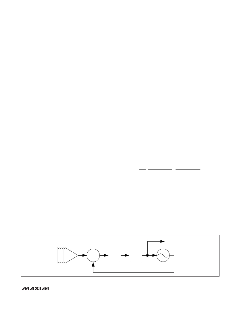
�FSK� Demodulator�
�The� FSK� demodulator� uses� an� integrated� 10.7MHz� PLL�
�that� tracks� the� input� RF� modulation� and� determines� the�
�difference� between� frequencies� as� logic-level� ones� and�
�zeros.� The� PLL� is� illustrated� in� Figure� 1.� The� input� to� the�
�PLL� comes� from� the� output� of� the� IF� limiting� amplifiers.�
�The� PLL� control� voltage� responds� to� changes� in� the� fre-�
�quency� of� the� input� signal� with� a� nominal� gain� of�
�2.2mV/kHz.� For� example,� an� FSK� peak-to-peak� devia-�
�tion� of� 50kHz� generates� a� 110mV� P-P� signal� on� the� con-�
�trol� line.� This� control� line� is� then� filtered� and� sliced� by�
�the� FSK� baseband� circuitry.�
�The� FSK� demodulator� PLL� requires� calibration� to� over-�
�come� variations� in� process,� voltage,� and� temperature.�
�For� more� information� on� calibrating� the� FSK� demodula-�
�tor,� see� the� Calibration� section.� The� maximum� calibra-�
�tion� time� is� 120μs.� In� DRX� mode,� the� FSK� demodulator�
�calibration� occurs� automatically� just� before� the� IC�
�enters� sleep� mode.�
�Crystal� Oscillator�
�The� XTAL� oscillator� in� the� MAX1471� is� used� to� generate�
�the� local� oscillator� (LO)� for� mixing� with� the� received� sig-�
�nal.� The� XTAL� oscillator� frequency� sets� the� received�
�signal� frequency� as:�
�f� RECEIVE� =� (f� XTAL� x� 32)� +10.7MHz�
�The� received� image� frequency� at:�
�is� suppressed� by� the� integrated� quadrature� image-�
�rejection� circuitry.�
�For� an� input� RF� frequency� of� 315MHz,� a� reference� fre-�
�quency� of� 9.509MHz� is� needed� for� a� 10.7MHz� IF� fre-�
�quency� (low-side� injection� is� required).� For� an� input� RF�
�frequency� of� 433.92MHz,� a� reference� frequency� of�
�13.2256MHz� is� required.�
�The� XTAL� oscillator� in� the� MAX1471� is� designed� to� pre-�
�sent� a� capacitance� of� approximately� 3pF� between� the�
�XTAL1� and� XTAL2.� If� a� crystal� designed� to� oscillate�
�with� a� different� load� capacitance� is� used,� the� crystal� is�
�pulled� away� from� its� stated� operating� frequency,� intro-�
�ducing� an� error� in� the� reference� frequency.� Crystals�
�designed� to� operate� with� higher� differential� load� capac-�
�itance� always� pull� the� reference� frequency� higher.�
�In� actuality,� the� oscillator� pulls� every� crystal.� The� crys-�
�tal’s� natural� frequency� is� really� below� its� specified� fre-�
�quency,� but� when� loaded� with� the� specified� load�
�capacitance,� the� crystal� is� pulled� and� oscillates� at� its�
�specified� frequency.� This� pulling� is� already� accounted�
�for� in� the� specification� of� the� load� capacitance.�
�Additional� pulling� can� be� calculated� if� the� electrical�
�parameters� of� the� crystal� are� known.� The� frequency�
�pulling� is� given� by:�
�1� 1� ?� 6�
�f� p� =� ?� ?� ?� � 10�
�2� ?� C� case� load� case� spec� ?�
�where:�
�f� p� is� the� amount� the� crystal� frequency� pulled� in� ppm.�
�C� m� is� the� motional� capacitance� of� the� crystal.�
�C� case� is� the� case� capacitance.�
�C� spec� is� the� specified� load� capacitance.�
�C� load� is� the� actual� load� capacitance.�
�When� the� crystal� is� loaded� as� specified,� i.e.,� C� load� =�
�C� spec� ,� the� frequency� pulling� equals� zero.�
�f� IMAGE� =� (f� XTAL� x� 32)� -10.7MHz�
�TO� FSK� BASEBAND� FILTER�
�AND� DATA� SLICER�
�IF�
�LIMITING�
�AMPS�
�PHASE�
�DETECTOR�
�CHARGE�
�PUMP�
�LOOP�
�FILTER�
�10.7MHz� VCO�
�2.2mV/kHz�
�Figure� 1.� FSK� Demodulator� PLL� Block� Diagram�
�______________________________________________________________________________________�
�11�
�相关PDF资料 |
PDF描述 |
|---|---|
| MICRF011BM | IC RCVR/DATA DEMOD RF/IF 14SOIC |
| AMB310908 | SENSOR REFL LONG H-TYPE |
| MICRF009BM | IC RECEIVER UHF LOW POWER 16SOIC |
| MICRF007BM | IC RECEIVER UHF LOW POWER 8SOIC |
| AMB345919 | SENSOR REFL LONG V TYPE W/OSC |
相关代理商/技术参数 |
参数描述 |
|---|---|
| MAX1471ATJ/V+ | 功能描述:射频接收器 315MHz/434MHz Low-Power 3V/5V ASK/FSK Superheterodyne Receiver RoHS:否 制造商:Skyworks Solutions, Inc. 类型:GPS Receiver 封装 / 箱体:QFN-24 工作频率:4.092 MHz 工作电源电压:3.3 V 封装:Reel |
| MAX1471ATJ/V+T | 功能描述:射频接收器 315MHz/434MHz Low-Power 3V/5V ASK/FSK Superheterodyne Receiver RoHS:否 制造商:Skyworks Solutions, Inc. 类型:GPS Receiver 封装 / 箱体:QFN-24 工作频率:4.092 MHz 工作电源电压:3.3 V 封装:Reel |
| MAX1471ATJ+ | 功能描述:射频接收器 315MHz/434MHz Superheterodyne Rcvr RoHS:否 制造商:Skyworks Solutions, Inc. 类型:GPS Receiver 封装 / 箱体:QFN-24 工作频率:4.092 MHz 工作电源电压:3.3 V 封装:Reel |
| MAX1471ATJ+T | 功能描述:射频接收器 315MHz/434MHz Superheterodyne Rcvr RoHS:否 制造商:Skyworks Solutions, Inc. 类型:GPS Receiver 封装 / 箱体:QFN-24 工作频率:4.092 MHz 工作电源电压:3.3 V 封装:Reel |
| MAX1471ATJ-C3N | 功能描述:射频接收器 315MHz/434MHz Superheterodyne Rcvr RoHS:否 制造商:Skyworks Solutions, Inc. 类型:GPS Receiver 封装 / 箱体:QFN-24 工作频率:4.092 MHz 工作电源电压:3.3 V 封装:Reel |
发布紧急采购,3分钟左右您将得到回复。