- 您现在的位置:买卖IC网 > Datasheet目录43 > MAX5952CUAX+ (Maxim Integrated)IC PSE CNTRLR FOR POE 36-SSOP Datasheet资料下载
参数资料
| 型号: | MAX5952CUAX+ |
| 厂商: | Maxim Integrated |
| 文件页数: | 7/50页 |
| 文件大小: | 1006K |
| 描述: | IC PSE CNTRLR FOR POE 36-SSOP |
| 产品培训模块: | Lead (SnPb) Finish for COTS Obsolescence Mitigation Program |
| 标准包装: | 30 |
| 类型: | 以太网供电控制器(PoE) |
| 应用: | 远程外设(工业控制,相机,数据访问) |
| 内部开关: | 无 |
| 工作温度: | 0°C ~ 85°C |
| 安装类型: | 表面贴装 |
| 封装/外壳: | 36-BSOP(0.295",7.50mm 宽) |
| 供应商设备封装: | 36-SSOP |
| 包装: | 管件 |
第1页第2页第3页第4页第5页第6页当前第7页第8页第9页第10页第11页第12页第13页第14页第15页第16页第17页第18页第19页第20页第21页第22页第23页第24页第25页第26页第27页第28页第29页第30页第31页第32页第33页第34页第35页第36页第37页第38页第39页第40页第41页第42页第43页第44页第45页第46页第47页第48页第49页第50页
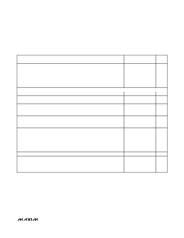
High-Power, Quad, PSE Controller
for Power-Over-Ethernet
_______________________________________________________________________________________ 7
ELECTRICAL CHARACTERISTICS (continued)
(V
AGND
= 32V to 60V, V
EE
= 0V, V
DD
to V
DGND
= +3.3V, all voltages are referenced to V
EE
, unless otherwise noted. Typical values are at
V
AGND
= +48V, V
DGND
= +48V, V
DD
= (V
DGND
+ 3.3V), T
A
= +25癈. Currents are positive when entering the pin and negative other-
wise.) (Note 2)
PARAMETER
SYMBOL
CONDITIONS
MIN
TYP
MAX
UNITS
Differential Nonlinearity
DNL
0.1
LSB
V
SENSE
= 100mV
5B
(91)
62
(98)
68
(104)
V
SENSE
= 250mV
F0
(240)
FC
(252)
108
(264)
ADC Absolute Accuracy
V
SENSE
= 400mV
186
(390)
196
(406)
1A6
(422)
Hex
(Dec)
TIMING CHARACTERISTICS (For 2-Wire Fast Mode, Note 10)
Serial-Clock Frequency
f
SCL
400
kHz
Bus Free Time Between a
STOP and START Condition
t
BUF
1.2
祍
Hold Time for a START
Condition
t
HD STA
0.6
祍
Low Period of the SCL Clock
t
LOW
1.2
祍
High Period of the SCL Clock
t
HIGH
0.6
祍
Setup Time for a Repeated
START Condition (Sr)
t
SU STA
0.6
祍
Data Hold Time
t
HD DAT
0
150
ns
Data in Setup Time
t
SU DAT
100
ns
Rise Time of Both SDA and
SCL Signals, Receiving
t
R
20 +
0.1C
B
300
ns
Fall Time of SDA Transmitting
t
F
20 +
0.1C
B
300
ns
Setup Time for STOP Condition
t
SU STO
0.6
祍
Capacitive Load for Each Bus
Line
C
B
400
pF
Pulse Width of Spike
Suppressed
t
SP
50
ns
Note 2: Limits to T
A
= -40癈 are guaranteed by design.
Note 3: Default values. The current-limit thresholds are programmed through the I
2
C-compatible serial interface (see the Register
Map and Description section).
Note 4: Functional test is performed over thermal shutdown entering test mode.
Note 5: Default values. The startup and fault times can be also programmed through the I
2
C serial interface (see the Register Map
and Description section).
Note 6: This is the default value. Threshold can be programmed through serial interface R23h[2:0].
Note 7: AC disconnect works only if (V
DD
- V
DGND
) e 3V and DGND is connected to AGND.
Note 8: t
DISC
can also be programmed through the serial interface (R16H) (see the Register Map and Description section).
Note 9: R
D
= (V
OUT_2
- V
OUT_1
) / (I
DET_2
- I
DET_1
). V
OUT_1
, V
OUT_2
, I
DET_2
and I
DET_1
represent the voltage at OUT_ and the cur-
rent at DET_ during phase 1 and 2 of the detection.
Note 10: Guaranteed by design. Not subject to production testing.
相关PDF资料 |
PDF描述 |
|---|---|
| MAX5953DUTM+ | IC INTERFACE 802.3AF 48TQFN |
| MAX5954LETX+T | IC PCI EXP/HOT-PLUG CTRLR 36TQFN |
| MAX5955BEEE+ | IC DUAL HOT-SWAP CTRLR 16-QSOP |
| MAX5957AETN+T | IC TRPL PCI EXP/HOT-PLUG 56-TQFN |
| MAX5960AECS+T | IC CTRLR HOT-PLUG QD 80-TQFP |
相关代理商/技术参数 |
参数描述 |
|---|---|
| MAX5952CUAX+ | 功能描述:热插拔功率分布 Quad PSE Controller for POE RoHS:否 制造商:Texas Instruments 产品:Controllers & Switches 电流限制: 电源电压-最大:7 V 电源电压-最小:- 0.3 V 工作温度范围: 功率耗散: 安装风格:SMD/SMT 封装 / 箱体:MSOP-8 封装:Tube |
| MAX5952CUAX+T | 功能描述:热插拔功率分布 Quad PSE Controller for POE RoHS:否 制造商:Texas Instruments 产品:Controllers & Switches 电流限制: 电源电压-最大:7 V 电源电压-最小:- 0.3 V 工作温度范围: 功率耗散: 安装风格:SMD/SMT 封装 / 箱体:MSOP-8 封装:Tube |
| MAX5952DEAX+ | 制造商:Maxim Integrated Products 功能描述:- Rail/Tube |
| MAX5952DEAX+T | 制造商:Maxim Integrated Products 功能描述:HIGH-POWER QUAD PSE CONTROLLER FOR - Tape and Reel |
| MAX5952DUAX+ | 制造商:Maxim Integrated Products 功能描述:- Rail/Tube |
发布紧急采购,3分钟左右您将得到回复。