- 您现在的位置:买卖IC网 > PDF目录16779 > MAX9888EVKIT+ (Maxim Integrated Products)KIT EVALUATION FOR MAX9888 PDF资料下载
参数资料
| 型号: | MAX9888EVKIT+ |
| 厂商: | Maxim Integrated Products |
| 文件页数: | 12/115页 |
| 文件大小: | 0K |
| 描述: | KIT EVALUATION FOR MAX9888 |
| 产品培训模块: | Lead (SnPb) Finish for COTS Obsolescence Mitigation Program |
| 标准包装: | 1 |
| 系列: | DirectDrive®, FLEXSOUND™ |
| 相关产品: | MAX9888EWY+T-ND - IC CODEC AUDIO FLEXSOUND 63WLP |
第1页第2页第3页第4页第5页第6页第7页第8页第9页第10页第11页当前第12页第13页第14页第15页第16页第17页第18页第19页第20页第21页第22页第23页第24页第25页第26页第27页第28页第29页第30页第31页第32页第33页第34页第35页第36页第37页第38页第39页第40页第41页第42页第43页第44页第45页第46页第47页第48页第49页第50页第51页第52页第53页第54页第55页第56页第57页第58页第59页第60页第61页第62页第63页第64页第65页第66页第67页第68页第69页第70页第71页第72页第73页第74页第75页第76页第77页第78页第79页第80页第81页第82页第83页第84页第85页第86页第87页第88页第89页第90页第91页第92页第93页第94页第95页第96页第97页第98页第99页第100页第101页第102页第103页第104页第105页第106页第107页第108页第109页第110页第111页第112页第113页第114页第115页
Stereo Audio CODEC
with FlexSound Technology
MAX9888
109
Filterless Class D Operation
Traditional Class D amplifiers require an output filter
to recover the audio signal from the amplifier’s output.
The filters add cost, increase the solution size of the
amplifier, and can decrease efficiency and THD+N
performance. The traditional PWM scheme uses large
differential output swings (2 x VDD peak to peak) and
causes large ripple currents. Any parasitic resistance in
the filter components results in a loss of power, lowering
the efficiency.
The IC does not require an output filter. The device relies
on the inherent inductance of the speaker coil and the
natural filtering of both the speaker and the human ear
to recover the audio component of the square-wave out-
put. Eliminating the output filter results in a smaller, less
costly, more efficient solution.
Because the frequency of the IC output is well beyond
the bandwidth of most speakers, voice coil move-
ment due to the square-wave frequency is very small.
Although this movement is small, a speaker not designed
to handle the additional power can be damaged. For
optimum results, use a speaker with a series inductance
> 10FH. Typical 8I speakers exhibit series inductances
in the 20FH to 100FH range.
RF Susceptibility
GSM radios transmit using time-division multiple access
(TDMA) with 217Hz intervals. The result is an RF signal
with strong amplitude modulation at 217Hz and its har-
monics that is easily demodulated by audio amplifiers.
The IC is designed specifically to reject RF signals; how-
ever, PCB layout has a large impact on the susceptibility
of the end product.
In RF applications, improvements to both layout and com-
ponent selection decrease the IC’s susceptibility to RF
noise and prevent RF signals from being demodulated into
audible noise. Trace lengths should be kept below 1/4 of
the wavelength of the RF frequency of interest. Minimizing
the trace lengths prevents them from functioning as anten-
nas and coupling RF signals into the IC. The wavelength
(
l) in meters is given by: l = c/f where c = 3 x 10⁸ m/s, and
f = the RF frequency of interest.
Route audio signals on middle layers of the PCB to allow
ground planes above and below to shield them from RF
interference. Ideally, the top and bottom layers of the
PCB should primarily be ground planes to create effec-
tive shielding.
Additional RF immunity can also be obtained by rely-
ing on the self-resonant frequency of capacitors as it
exhibits a frequency response similar to a notch filter.
Depending on the manufacturer, 10pF to 20pF capaci-
tors typically exhibit self resonance at the RF frequencies
of interest. These capacitors, when placed at the input
pins, can effectively shunt the RF noise to ground. For
these capacitors to be effective, they must have a low-
impedance, low-inductance path to the ground plane.
Avoid using microvias to connect to the ground plane
whenever possible as these vias do not conduct well at
RF frequencies.
Startup/Shutdown Sequencing
To ensure proper device initialization and minimal click-
and-pop, program the IC’s SHDN = 1 after configuring all
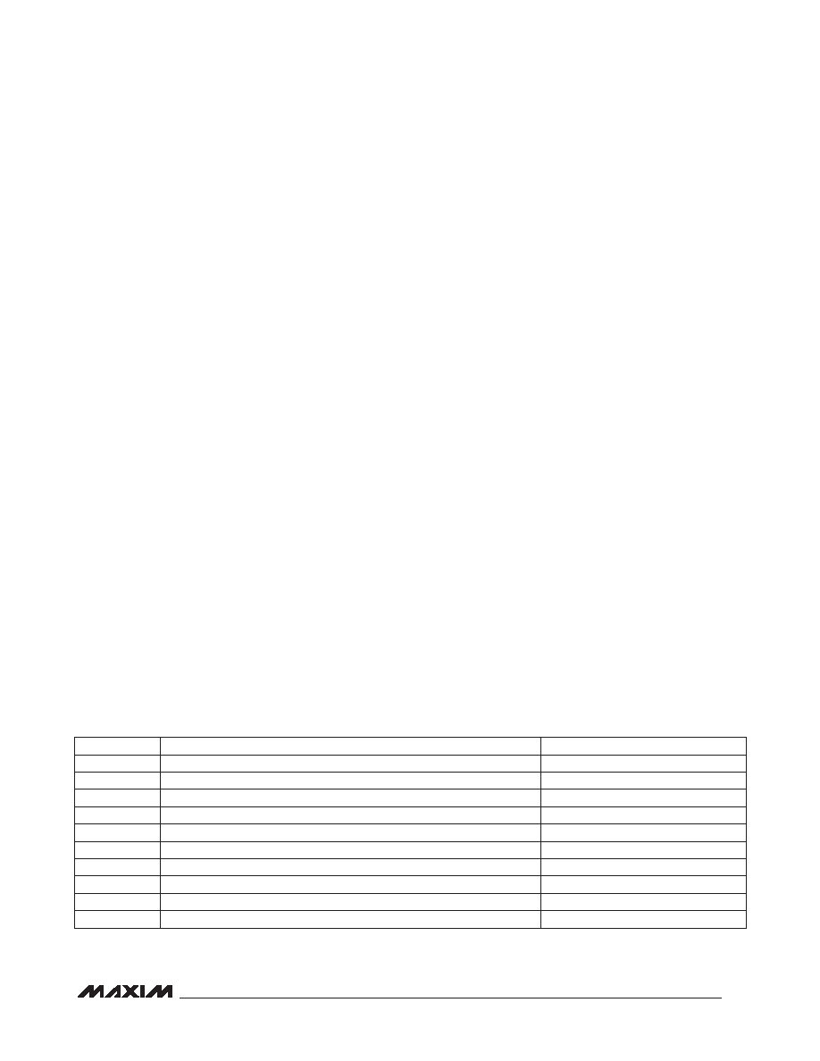
registers. Table 39 lists an example startup sequence for
the device. To shut down the IC, simply set SHDN = 0.
Table 39. Example Startup Sequence
SEQUENCE
DESCRIPTION
REGISTERS
1
Ensure SHDN = 0
0x4C
2
Configure clocks
0x10 to 0x13, 0x19 to 0x1B
3
Configure digital audio interface
0x14 to 0x17, 0x1C to 0x1F
4
Configure digital signal processing
0x18, 0x20, 0x3D to 0x44
5
Load coefficients
0x50 to 0xC7
6
Configure mixers
0x21 to 0x29
7
Configure gain and volume controls
0x2A to 0x3C
8
Configure miscellaneous functions
0x45 to 0x49
9
Enable desired functions
0x4A, 0x4B
10
Set SHDN = 1
0x4C
相关PDF资料 |
PDF描述 |
|---|---|
| H3AAH-3418G | IDC CABLE - HSC34H/AE34G/HSC34H |
| EBM22DRAI | CONN EDGECARD 44POS R/A .156 SLD |
| RNF-100-1/8-GN-STK | HEAT SHRINK TUBING |
| RSC06DREF-S13 | CONN EDGECARD 12POS .100 EXTEND |
| GEC26DRXN-S734 | CONN EDGECARD 52POS DIP .100 SLD |
相关代理商/技术参数 |
参数描述 |
|---|---|
| MAX9888EVKIT+ | 功能描述:音频 IC 开发工具 MAX9888 Eval Kit RoHS:否 制造商:Texas Instruments 产品:Evaluation Kits 类型:Audio Amplifiers 工具用于评估:TAS5614L 工作电源电压:12 V to 38 V |
| MAX9888EWY+T | 功能描述:接口—CODEC Stereo Audio CODEC RoHS:否 制造商:Texas Instruments 类型: 分辨率: 转换速率:48 kSPs 接口类型:I2C ADC 数量:2 DAC 数量:4 工作电源电压:1.8 V, 2.1 V, 2.3 V to 5.5 V 最大工作温度:+ 85 C 安装风格:SMD/SMT 封装 / 箱体:DSBGA-81 封装:Reel |
| MAX9889EWO+T | 功能描述:接口—CODEC RoHS:否 制造商:Texas Instruments 类型: 分辨率: 转换速率:48 kSPs 接口类型:I2C ADC 数量:2 DAC 数量:4 工作电源电压:1.8 V, 2.1 V, 2.3 V to 5.5 V 最大工作温度:+ 85 C 安装风格:SMD/SMT 封装 / 箱体:DSBGA-81 封装:Reel |
| MAX988ESA | 功能描述:校验器 IC Single uPower Comparator RoHS:否 制造商:STMicroelectronics 产品: 比较器类型: 通道数量: 输出类型:Push-Pull 电源电压-最大:5.5 V 电源电压-最小:1.1 V 补偿电压(最大值):6 mV 电源电流(最大值):1350 nA 响应时间: 最大工作温度:+ 125 C 安装风格:SMD/SMT 封装 / 箱体:SC-70-5 封装:Reel |
| MAX988ESA+ | 功能描述:校验器 IC Single uPower Comparator RoHS:否 制造商:STMicroelectronics 产品: 比较器类型: 通道数量: 输出类型:Push-Pull 电源电压-最大:5.5 V 电源电压-最小:1.1 V 补偿电压(最大值):6 mV 电源电流(最大值):1350 nA 响应时间: 最大工作温度:+ 125 C 安装风格:SMD/SMT 封装 / 箱体:SC-70-5 封装:Reel |
发布紧急采购,3分钟左右您将得到回复。