- 您现在的位置:买卖IC网 > PDF目录11718 > MC33560DTB (ON Semiconductor)OC PWR MGMT READERS/CPLR 24TSSOP PDF资料下载
参数资料
| 型号: | MC33560DTB |
| 厂商: | ON Semiconductor |
| 文件页数: | 7/26页 |
| 文件大小: | 0K |
| 描述: | OC PWR MGMT READERS/CPLR 24TSSOP |
| 标准包装: | 62 |
| 系列: | * |
| 应用: | * |
| 接口: | * |
| 电源电压: | * |
| 封装/外壳: | 24-TSSOP(0.220",5.60mm 宽) |
| 供应商设备封装: | 24-TSSOP |
| 包装: | 管件 |
| 安装类型: | 表面贴装 |
MC33560
http://onsemi.com
15
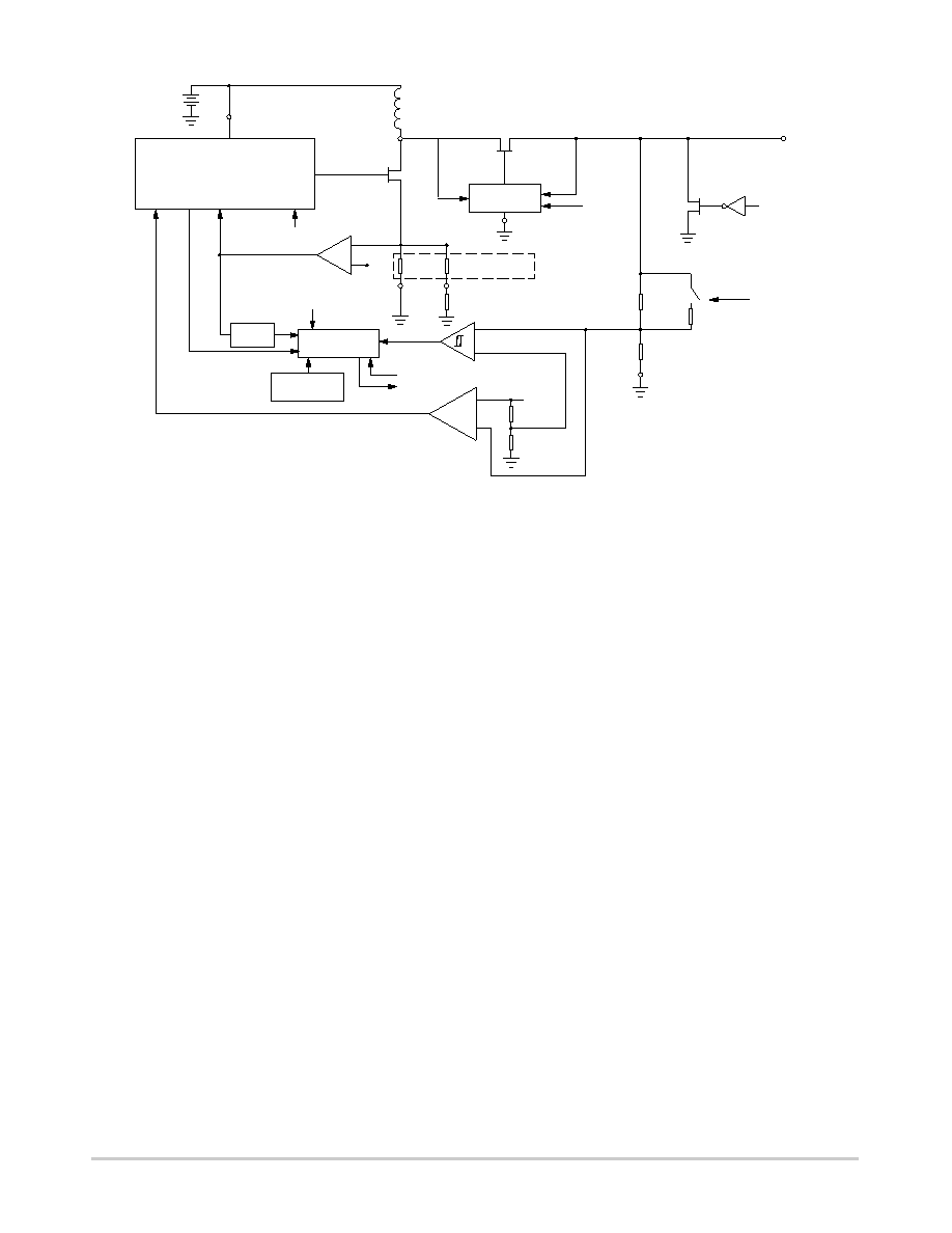
Figure 22. DCDC Converter Functional Block
PWN
Low Side
FEED
VBAT
ON /OFF
L1
BACK CLOCK OFF
STOP
ON /OFF
+
+
LOGIC
AND
COUNTER
OVER TEMP
DETECTION
DIGITAL
FILTER
+
ON /OFF
RECTIFIER
CONTROL
Switch
120 mV
PGND
ILIM
RLIM (external)
Internal
resistors
2
W
0.5
W
ON /OFF
Rectifier Switch
CRDVCC
Active pulldown
switch
3V/5V
CRDGND
VREF
UNDER VOLTAGE
DETECTOR
ERROR
AMP.
VBATOK
CONVERTER
FAULT
CRDGND
ILIMCOMP
The overcurrent and undervoltage protection features are
complementary, and will shut the circuit off either if the
overcurrent is high enough to bring the CRDVCC output
below the preset threshold, either after 160 ms (typ.)
In addition, the DCDC converter will be allowed to start
only if the battery supply voltage is high enough to allow
normal operation (1.8 V).
The undervoltage comparator has a hysteresis and a delay
of typically 20 ms to ensure stable operation. The current
detector is a comparator associated with two resistors: one
2.0
W attached to PGND and usually connected to analog
ground, and a 0.5
W attached to ILIM, usually connected to
ground through an external resistor to adjust the maximum
peak current. The voltage developed across this resistor
network is then compared to a 120 mV (typical) reference
voltage,
and
the
comparator
output
performs
a
cyclebycycle peak current limitation by switching off the
low side transistor when the voltage exceeds 120 mV.
The internal ILIMCOMP signal is monitored to stop the
converter if current limitation is continuously detected
during 160 ms (typical). This allows normal operation with
high filtering capacitance and low peak current, even at
converter startup. As a result, a short circuit to ground on the
card connector or a continuous overcurrent is reported by
RDYMOD 160 ms (typical) after powerup.
Unexpected Card Extraction: The MC33560 detects
card extraction and runs a powerdown sequence if card
power is still on when extraction occurs. An active pulldown
switch clamps CRDVCC to GND within 150
ms (max) after
extraction is detected. The external capacitors will then be
discharged. With typical capacitor values of 10
mF and 47 nF
as indicated in the application schematic, the time needed to
discharge CRDVCC to a voltage below 0.4 V can be
estimated to less than 750
ms. The total time aftercard
extraction detection until CRDVCC reaches 0.4 V is then
estimated to 900
ms (maximum). All smartcard connector
contacts will be deactivated before CRDVCC deactivation.
This ensures that no electrical damage will be caused to the
smartcard under abnormal extraction conditions.
3.0 V/5.0 V Programming: It is possible to set the card
supply voltage to 3.0 V or 5.0 V at any time, before DCDC
converter start, or during converter operation. When
switching from 3.0 V to 5.0 V, a 160 ms (typical) delay
blanks the undervoltage fault detection to allow filter
capacitor charging.
PWM: The freerunning integrated oscillator has two
working modes:
Variable onstate and fixed frequency (typically 120 KHz)
for average to heavy loads.
Variable onstate and variable frequency for light loads.
The frequency can be as low as a few kHz if no load is
connected to CRDVCC.
The charging current of the timing capacitor is related to
the VBAT supply voltage, to allow better line regulation, and
to increase stability.
Filtering Capacitor: A high value allows efficient
filtering of card current spikes. Low values allow low startup
charging current. Care must be taken not to combine low
capacitor value with high current limiting, as this can
generate high ripple. Usual values range from 4.7
mF to
47
mF, depending on current limiting.
Selecting the External Components L1 and RLIM:
The choice of inductor L1 and resistor R4 is made by using
相关PDF资料 |
PDF描述 |
|---|---|
| MC100E446FNR2 | IC CONV 4BIT SER/PAR ECL 28-PLCC |
| D38999/26WG41SN | CONN PLUG 41POS STRAIGHT W/SCKT |
| D38999/24JD18HN | CONN RCPT 18POS JAM NUT W/PINS |
| MCZ33797EK | IC SQUIB DRIVER 4-CH 32-SOIC |
| MCZ33889BEG | IC SYSTEM BASIS W/CAN 28-SOIC |
相关代理商/技术参数 |
参数描述 |
|---|---|
| MC33560DTBR2 | 功能描述:输入/输出控制器接口集成电路 3V/5V Smartcard RoHS:否 制造商:Silicon Labs 产品: 输入/输出端数量: 工作电源电压: 最大工作温度:+ 85 C 最小工作温度:- 40 C 安装风格:SMD/SMT 封装 / 箱体:QFN-64 封装:Tray |
| MC33560DTBR2G | 功能描述:输入/输出控制器接口集成电路 3V/5V Smartcard Power Management RoHS:否 制造商:Silicon Labs 产品: 输入/输出端数量: 工作电源电压: 最大工作温度:+ 85 C 最小工作温度:- 40 C 安装风格:SMD/SMT 封装 / 箱体:QFN-64 封装:Tray |
| MC33560DW | 功能描述:输入/输出控制器接口集成电路 3V/5V Smartcard RoHS:否 制造商:Silicon Labs 产品: 输入/输出端数量: 工作电源电压: 最大工作温度:+ 85 C 最小工作温度:- 40 C 安装风格:SMD/SMT 封装 / 箱体:QFN-64 封装:Tray |
| MC33560DWR2 | 功能描述:输入/输出控制器接口集成电路 3V/5V Smartcard RoHS:否 制造商:Silicon Labs 产品: 输入/输出端数量: 工作电源电压: 最大工作温度:+ 85 C 最小工作温度:- 40 C 安装风格:SMD/SMT 封装 / 箱体:QFN-64 封装:Tray |
| MC33560DWR2G | 功能描述:输入/输出控制器接口集成电路 3V/5V Smartcard Power Management RoHS:否 制造商:Silicon Labs 产品: 输入/输出端数量: 工作电源电压: 最大工作温度:+ 85 C 最小工作温度:- 40 C 安装风格:SMD/SMT 封装 / 箱体:QFN-64 封装:Tray |
发布紧急采购,3分钟左右您将得到回复。