- 您现在的位置:买卖IC网 > PDF目录20771 > MC34844EPR2 (Freescale Semiconductor)IC LED DVR BACKLIGHT 10CH 32QFN PDF资料下载
参数资料
| 型号: | MC34844EPR2 |
| 厂商: | Freescale Semiconductor |
| 文件页数: | 17/62页 |
| 文件大小: | 0K |
| 描述: | IC LED DVR BACKLIGHT 10CH 32QFN |
| 视频文件: | LED backlighting with MC34844 |
| 标准包装: | 2,500 |
| 恒定电流: | 是 |
| 拓扑: | PWM,升压(升压) |
| 输出数: | 10 |
| 内部驱动器: | 是 |
| 类型 - 主要: | 背光 |
| 频率: | 可调节/可选择 |
| 电源电压: | 7 V ~ 28 V |
| 输出电压: | 8 V ~ 60 V |
| 安装类型: | 表面贴装 |
| 封装/外壳: | 32-VFQFN 裸露焊盘 |
| 供应商设备封装: | 32-QFN 裸露焊盘(5x5) |
| 包装: | 带卷 (TR) |
| 工作温度: | -40°C ~ 105°C |
| 配用: | KIT34844EPEVME-ND - BOARD EVAL 10CH MC34844 LED DVR |
第1页第2页第3页第4页第5页第6页第7页第8页第9页第10页第11页第12页第13页第14页第15页第16页当前第17页第18页第19页第20页第21页第22页第23页第24页第25页第26页第27页第28页第29页第30页第31页第32页第33页第34页第35页第36页第37页第38页第39页第40页第41页第42页第43页第44页第45页第46页第47页第48页第49页第50页第51页第52页第53页第54页第55页第56页第57页第58页第59页第60页第61页第62页
�� �
�
�MC34844�
�FUNCTIONAL� DESCRIPTION�
�FUNCTIONAL� INTERNAL� BLOCK� DESCRIPTION�
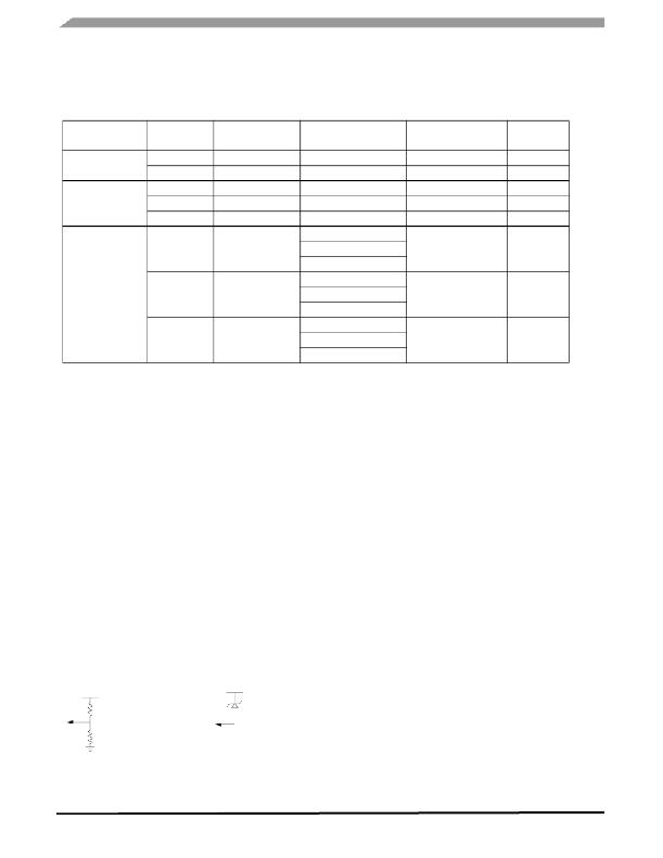
�Table� 5.� Operation� Current� Consumption� Modes�
�Mode�
�Manual�
�SM� Bus�
�EN� Pin�
�Low�
�High�
�Low�
�Low�
�Low�
�Low�
�SCK/SDA� Pins�
�Low�
�Low�
�Low� (>� 27� ms)�
�Active�
�Active�
�X�
�I� 2� C� Bit� Command�
�N/A�
�N/A�
�EN� bit� =� X�
�EN� bit� =� 0�
�EN� bit� =� 1�
�SETI2C� bit� =� 1�
�CLRI2C� bit� =� 0�
�Current� Consumption�
�Mode�
�Shutdown�
�Operational�
�Shutdown�
�Sleep�
�Operational�
�I� 2� C� Low� Power�
�(Shutdown)�
�Comments�
�Part� Doesn’t�
�Wake-up�
�EN� bit� =� X�
�SETI2C� bit� =� 1�
�I� 2� C�
�High�
�X�
�CLRI2C� bit� =� 0�
�Sleep�
�EN� bit� =� 0�
�SETI2C� bit� =� 1�
�High�
�X�
�CLRI2C� bit� =� 0�
�Operational�
�EN� bit� =� 1�
�BOOST�
�The� integrated� boost� converter� operates� in� non-�
�synchronous� mode� and� integrates� a� 2.5� A� FET.� An� integrated�
�sense� circuit� is� used� to� sense� the� voltage� at� the� LED� current�
�mirror� inputs� and� automatically� sets� the� boost� output� voltage�
�(DHC)� to� the� minimum� voltage� needed� to� keep� all� LEDs�
�biased� with� the� required� current.� The� DHC� is� designed� to�
�operate� under� specific� pulse� width� conditions� in� the� LED�
�drivers.� It� operates� for� pulse� widths� higher� than� 4.0� μ� s�
�If� the� pulse� widths� are� shorter� than� specified,� the� DHC�
�circuit� will� not� operate� and� the� voltage� across� the� LED� drivers�
�will� increase� to� a� value� given� by� the� OVP� minus� the� total� LED�
�voltage� in� the� LED� string.� Therefore� it� is� imperative� to� select�
�the� proper� OVP� level� to� minimize� power� dissipation.�
�The� OVP� can� be� set� from� 11� to� 62� V,� ~4.0� V� spaced,� using�
�the� I� 2� C� interface� (OVP� Register).� If� I� 2� C� capability� is� not�
�present,� the� OVP� can� be� controlled� by� a� resistor� divider�
�connected� from� VOUT� to� GND� with� its� mid� point� tied� to� A0/�
�SEN� pin� (threshold� =� 6.5� V).� During� an� OVP� condition,� the�
�output� voltage� will� go� to� the� OVP� level� which� is� programmed�
�via� the� I� 2� C� interface� or� settled� by� a� resistor� divider� on� A0/SEN�
�pin,� or� by� a� zener� diode.� The� formulas� to� calculate� the�
�hardware� OVP� using� any� of� the� two� methods� are� as� follows:�
�HARDWARE� OVP� :�
�The� OVP� value� should� be� set� to� greater� than� the� maximum�
�LED� voltage� over� the� whole� temperature� range.� A� good�
�practice� is� to� set� it� 5.0� V� or� so� above� the� max� LED� voltage.�
�The� boost� converter� also� features� internal� Over-current�
�Protection� (OCP)� and� has� a� user� programmable� Over-�
�voltage� Protection� (OVP).�
�The� OCP� operates� on� a� cycle� by� cycle� basis.� However,� if�
�the� OCP� condition� remains� for� more� than� 10� ms� then� the�
�device� turns� off� the� LED� Drivers,� the� Boost� goes� to� Sleep�
�mode� and� the� output� FAULT� pin� goes� into� high-impedance.�
�The� device� can� only� be� restarted� by� recycling� the� enable� or�
�creating� a� Power� On� Reset� (POR).�
�The� user� can� program� the� boost� frequency� by� I� 2� C�
�(BST[1:0])� only� after� the� IC� is� powered� up� and� before� the�
�boost� circuit� is� turned� ON� for� the� first� time� (PWM� pin� low� to�
�high).� This� sequence� avoids� boost� frequency� to� be� changed�
�inadvertently� during� operation.� The� first� I� 2� C� command� has� to�
�wait� for� 5.0� ms� after� the� part� is� turned� ON,� in� order� to� allow�
�sufficient� time� for� the� device� power� up� sequence� to� be�
�completed.�
�The� boost� controller� has� an� integral� track� and� hold�
�amplifier� with� indefinite� hold� time� capability,� to� enable�
�Method� 1�
�V� OUT�
�Method� 2�
�immediate� LED� on� cycles� after� extended� off� times.� During�
�extended� off� times,� the� external� LEDs� cool� down� from� their�
�normal� quiescent� operating� temperature� and� thereby�
�RUPPER�
�A0/SEN�
�VZENER2�
�experience� a� forward� voltage� change,� typically� an� increase� in�
�the� forward� voltage.� This� change� can� be� significant� for�
�A0/SEN�
�RLOWER�
�OVP� =� V� ZENER2� +� 6.5� V�
�applications� with� a� large� number� of� series� LEDs� in� a� string�
�operating� at� high� current.� If� the� boost� controller� did� not� track�
�OVP� =� 6.5� V� [(R� UPPER� /� R� LOWER� )� +� 1]� +� (100E-6� x� R� UPPER� )�
�this� increased� change,� the� potential� on� the� LED� drivers� would�
�saturate� for� a� few� cycles� once� the� LED� channels� are� re-�
�enabled.�
�34844�
�Analog� Integrated� Circuit� Device� Data�
�17�
�Freescale� Semiconductor�
�相关PDF资料 |
PDF描述 |
|---|---|
| HCC60DRES-S93 | CONN EDGECARD 120PS .100 EYELET |
| HBC60DRES-S93 | CONN EDGECARD 120PS .100 EYELET |
| TAP686K025CRW | CAP TANT 68UF 25V 10% RADIAL |
| GSC50DRYS-S93 | CONN EDGECARD 100PS DIP .100 SLD |
| GMC50DRYS-S93 | CONN EDGECARD 100PS DIP .100 SLD |
相关代理商/技术参数 |
参数描述 |
|---|---|
| MC34845 | 制造商:SPC Multicomp 功能描述:RECEPTACLE FREE 16WAY 制造商:SPC Multicomp 功能描述:RECEPTACLE, FREE, 16WAY |
| MC34845AEP | 功能描述:LED照明驱动器 6-Ch LED Backlt Driver RoHS:否 制造商:STMicroelectronics 输入电压:11.5 V to 23 V 工作频率: 最大电源电流:1.7 mA 输出电流: 最大工作温度: 安装风格:SMD/SMT 封装 / 箱体:SO-16N |
| MC34845AEPR2 | 功能描述:LED照明驱动器 6-Ch LED Backlt Driver RoHS:否 制造商:STMicroelectronics 输入电压:11.5 V to 23 V 工作频率: 最大电源电流:1.7 mA 输出电流: 最大工作温度: 安装风格:SMD/SMT 封装 / 箱体:SO-16N |
| MC34845BEP | 功能描述:USB 接口集成电路 6-Ch LED Backlt Driver RoHS:否 制造商:Cypress Semiconductor 产品:USB 2.0 数据速率: 接口类型:SPI 工作电源电压:3.15 V to 3.45 V 工作电源电流: 最大工作温度:+ 85 C 安装风格:SMD/SMT 封装 / 箱体:WLCSP-20 |
| MC34845BEPR2 | 功能描述:USB 接口集成电路 6-Ch LED Backlt Driver RoHS:否 制造商:Cypress Semiconductor 产品:USB 2.0 数据速率: 接口类型:SPI 工作电源电压:3.15 V to 3.45 V 工作电源电流: 最大工作温度:+ 85 C 安装风格:SMD/SMT 封装 / 箱体:WLCSP-20 |
发布紧急采购,3分钟左右您将得到回复。