- 您现在的位置:买卖IC网 > PDF目录11943 > MC68HC705C9AFNE (Freescale Semiconductor)IC MCU 8BIT 44-PLCC PDF资料下载
参数资料
| 型号: | MC68HC705C9AFNE |
| 厂商: | Freescale Semiconductor |
| 文件页数: | 80/118页 |
| 文件大小: | 0K |
| 描述: | IC MCU 8BIT 44-PLCC |
| 标准包装: | 26 |
| 系列: | HC05 |
| 核心处理器: | HC05 |
| 芯体尺寸: | 8-位 |
| 速度: | 2.1MHz |
| 连通性: | SCI,SPI |
| 外围设备: | POR,WDT |
| 输入/输出数: | 24 |
| 程序存储器容量: | 16KB(16K x 8) |
| 程序存储器类型: | OTP |
| RAM 容量: | 352 x 8 |
| 电压 - 电源 (Vcc/Vdd): | 3 V ~ 5.5 V |
| 振荡器型: | 内部 |
| 工作温度: | 0°C ~ 70°C |
| 封装/外壳: | 44-LCC(J 形引线) |
| 包装: | 管件 |
第1页第2页第3页第4页第5页第6页第7页第8页第9页第10页第11页第12页第13页第14页第15页第16页第17页第18页第19页第20页第21页第22页第23页第24页第25页第26页第27页第28页第29页第30页第31页第32页第33页第34页第35页第36页第37页第38页第39页第40页第41页第42页第43页第44页第45页第46页第47页第48页第49页第50页第51页第52页第53页第54页第55页第56页第57页第58页第59页第60页第61页第62页第63页第64页第65页第66页第67页第68页第69页第70页第71页第72页第73页第74页第75页第76页第77页第78页第79页当前第80页第81页第82页第83页第84页第85页第86页第87页第88页第89页第90页第91页第92页第93页第94页第95页第96页第97页第98页第99页第100页第101页第102页第103页第104页第105页第106页第107页第108页第109页第110页第111页第112页第113页第114页第115页第116页第117页第118页
Serial Communications Interface (SCI)
MC68HC05C9A Advance Information Data Sheet, Rev. 4.1
64
Freescale Semiconductor
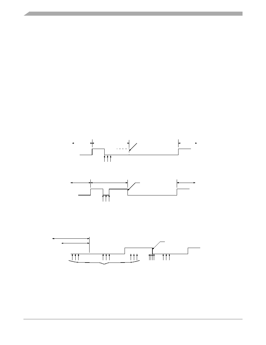
9.11 Start Bit Detection
When the input (idle) line is detected low, it is tested for three more sample times (referred to as the start
edge verification samples in Figure 9-4). If at least two of these three verification samples detect a logic
0, a valid start bit has been detected; otherwise, the line is assumed to be idle. A noise flag is set if all
three verification samples do not detect a logic 0. Thus, a valid start bit could be assumed with a set noise
flag present.
If a framing error has occurred without detection of a break (10 0s for
8-bit format or 11 0s for 9-bit format), the circuit continues to operate as if there actually was a stop bit,
and the start edge will be placed artificially. The last bit received in the data shift register is inverted to a
logic 1, and the three logic 1 start qualifiers (shown in Figure 9-4) are forced into the sample shift register
during the interval when detection of a start bit is anticipated (see Figure 9-6); therefore, the start bit will
be accepted no sooner than it is anticipated.
If the receiver detects that a break (RDRF = 1, FE = 1, receiver data register = $003B) produced the
framing error, the start bit will not be artificially induced and the receiver must actually detect a logic 1
before the start bit can be recognized (see Figure 9-7).
Figure 9-6. SCI Artificial Start Following a Frame Error
Figure 9-7. SCI Start Bit Following a Break
DATA
EXPECTED STOP
DATA SAMPLES
ARTIFICIAL EDGE
START BIT
DATA
RDI
DATA
EXPECTED STOP
DATA SAMPLES
START EDGE
START BIT
DATA
RDI
a) Case 1: Receive line low during artificial edge
b) Case 2: Receive line high during expected start edge
EXPECTED STOP
DATA SAMPLES
DETECTED AS VALID START EDGE
START BIT
RDI
BREAK
START
QUALIFIERS
START EDGE
VERIFICATION
SAMPLES
相关PDF资料 |
PDF描述 |
|---|---|
| VI-B5N-CU-F2 | CONVERTER MOD DC/DC 18.5V 200W |
| MC68HC705C8AVFNE | IC MCU 8BIT 44-PLCC |
| VJ1825Y823JBGAT4X | CAP CER 0.082UF 1KV 5% X7R 1825 |
| VI-B5M-CU-F3 | CONVERTER MOD DC/DC 10V 200W |
| MC68HCP11E0FNE | IC MCU 8BIT 52-PLCC |
相关代理商/技术参数 |
参数描述 |
|---|---|
| MC68HC705C9AVFNE | 功能描述:8位微控制器 -MCU 8B MCU 352 BYTES RAM RoHS:否 制造商:Silicon Labs 核心:8051 处理器系列:C8051F39x 数据总线宽度:8 bit 最大时钟频率:50 MHz 程序存储器大小:16 KB 数据 RAM 大小:1 KB 片上 ADC:Yes 工作电源电压:1.8 V to 3.6 V 工作温度范围:- 40 C to + 105 C 封装 / 箱体:QFN-20 安装风格:SMD/SMT |
| MC68HC705E6CDW | 制造商:Motorola Inc 功能描述: 制造商:MOTOROLA 功能描述: |
| MC68HC705G1B | 制造商:Rochester Electronics LLC 功能描述:- Bulk |
| MC68HC705J1A | 制造商:Freescale Semiconductor 功能描述: |
| MC68HC705J1ACDW | 功能描述:IC MCU 4MHZ 1.2K OTP 20-SOIC RoHS:否 类别:集成电路 (IC) >> 嵌入式 - 微控制器, 系列:HC05 其它有关文件:STM32F101T8 View All Specifications 特色产品:STM32 32-bit Cortex MCUs 标准包装:490 系列:STM32 F1 核心处理器:ARM? Cortex?-M3 芯体尺寸:32-位 速度:36MHz 连通性:I²C,IrDA,LIN,SPI,UART/USART 外围设备:DMA,PDR,POR,PVD,PWM,温度传感器,WDT 输入/输出数:26 程序存储器容量:64KB(64K x 8) 程序存储器类型:闪存 EEPROM 大小:- RAM 容量:10K x 8 电压 - 电源 (Vcc/Vdd):2 V ~ 3.6 V 数据转换器:A/D 10x12b 振荡器型:内部 工作温度:-40°C ~ 85°C 封装/外壳:36-VFQFN,36-VFQFPN 包装:托盘 配用:497-10030-ND - STARTER KIT FOR STM32497-8853-ND - BOARD DEMO STM32 UNIV USB-UUSCIKSDKSTM32-PL-ND - KIT IAR KICKSTART STM32 CORTEXM3497-8512-ND - KIT STARTER FOR STM32F10XE MCU497-8505-ND - KIT STARTER FOR STM32F10XE MCU497-8304-ND - KIT STM32 MOTOR DRIVER BLDC497-6438-ND - BOARD EVALUTION FOR STM32 512K497-6289-ND - KIT PERFORMANCE STICK FOR STM32MCBSTM32UME-ND - BOARD EVAL MCBSTM32 + ULINK-MEMCBSTM32U-ND - BOARD EVAL MCBSTM32 + ULINK2更多... 其它名称:497-9032STM32F101T8U6-ND |
发布紧急采购,3分钟左右您将得到回复。