- 您现在的位置:买卖IC网 > PDF目录16673 > MCP2150DM (Microchip Technology)BOARD DEMO FOR MCP2150 PDF资料下载
参数资料
| 型号: | MCP2150DM |
| 厂商: | Microchip Technology |
| 文件页数: | 10/52页 |
| 文件大小: | 0K |
| 描述: | BOARD DEMO FOR MCP2150 |
| 标准包装: | 1 |
| 主要目的: | 接口,IrDA |
| 嵌入式: | 是,MCU,8 位 |
| 已用 IC / 零件: | MCP2150 |
| 主要属性: | 带 PIC18F MCU 的 IrDA 控制器 |
| 次要属性: | USB 接口 |
| 已供物品: | 板 |
| 产品目录页面: | 685 (CN2011-ZH PDF) |
第1页第2页第3页第4页第5页第6页第7页第8页第9页当前第10页第11页第12页第13页第14页第15页第16页第17页第18页第19页第20页第21页第22页第23页第24页第25页第26页第27页第28页第29页第30页第31页第32页第33页第34页第35页第36页第37页第38页第39页第40页第41页第42页第43页第44页第45页第46页第47页第48页第49页第50页第51页第52页
MCP2150
DS21655B-page 18
Preliminary
2002 Microchip Technology Inc.
2.10
Operation
The MCP2150 emulates a null modem connection. The
application on the DTE device sees a virtual serial port.
This serial port emulation is provided by the IrDA stan-
dard protocols. The link between the DTE device and
the embedded application is made using the
MCP2150. The connection between the MCP2150 and
the embedded application is wired as if there were a
null modem connection.
The Carrier Detect (CD) signal of the MCP2150 is used
to indicate that a valid IrDA standard infrared link has
been established between the MCP2150 and the Pri-
mary device. The CD signal should be monitored
closely to make sure that any communication tasks can
be completed. The MCP2150 DSR signal indicates that
the device has powered-up, successfully initialized and
is ready for service. This signal is intended to be con-
nected to the DSR input of the Host Controller. If the
Host Controller was directly connected to an IrDA stan-
dard Primary device using a serial cable (the MCP2150
is not present), the Host Controller would be connected
to the Primary device’s DTR output signal.
The MCP2150 generates the CTS signal locally
because of buffer limitations.
2.10.1
HARDWARE HANDSHAKING
The MCP2150 uses a 64-byte buffer for incoming data
from the IR Host. Another 64-byte buffer is provided to
buffer data from the UART serial port. When an IR
packet begins the IrComm, the MCP2150 handles IR
data exclusively (the UART serial port buffer is not
available). A hardware handshaking pin (CTS) is pro-
vided to inhibit the Host Controller from sending serial
data while IR Data is being sent or received.
2.10.2
BUFFERS AND THROUGHPUT
The maximum IR data rate of the MCP2150 is
115.2 kbaud. The actual throughput will be less, due to
several factors. The most significant factors are under
the control of the developer. One factor beyond the
control of the designer is the overhead associated with
the IrDA standard. The MCP2150 uses a fixed data
block size of 64 bytes. To carry 64 bytes of data, the
MCP2150 must send 72 bytes (64+8). The additional 8
bytes are used by the protocol. When the Primary
device receives the frame, it must wait for a minimum
latency period before sending a packet of its own. This
turnaround time is set by IrLAP when the parameters of
the link are negotiated. A common turnaround time is
1 ms, although longer and shorter times may be
encountered. 1 ms represents approximately 12 byte
times at a data rate of 115.2 kbaud. The minimum size
frame the Primary device can respond with is 6 bytes.
The MCP2150 will add the 12 byte-time latency on its
own, again assuming a 1 ms latency. This means that
the maximum throughput will be 64 data bytes out of a
total of 64 + 38 byte times. Thus, the maximum theoret-
ical throughput will be limited to about 64/(64+38)=63%
of the IR data rate. Actual maximum throughput will be
dependent
on
both
the
MCP2150
and
the
characteristics of the Primary device.
The most significant factor in data throughput is how
well the data frames are filled. If only 1 byte is sent at a
time, then the maximum throughput is 1/(1+38)=2.5%
of the IR data rate. The best way to maximize through-
put is to align the amounts of data with the packet size
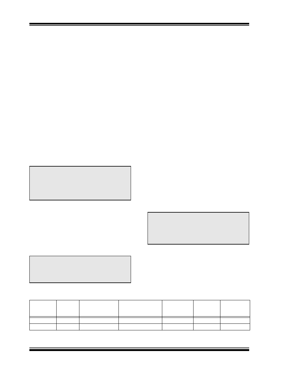
of the MCP2150. Throughput examples are shown in
TABLE 2-4:
THEORETICAL IrDA STANDARD THROUGHPUT EXAMPLES @ 115.2 KBAUD
Note 1: The
MCP2150
generates
non-data
signals locally.
2: Only transceiver’s TXD and RXD signals
are carried back and forth to the Primary
device. The MCP2150 emulates a 3-wire
serial connection (TXD, RXD and GND).
Note:
When the CTS output from the IrComm is
high, no data should be sent from the Host
Controller. The UART FIFO will store up to
2 bytes. Any additional data bytes will be
lost.
Note:
IrDA throughput is based on many factors
associated with characteristics of the Pri-
mary and Secondary devices. These char-
acteristics may cause your application
throughput to be less than the theoretical
example shown in Table 2-4.
MCP2150
Data Packet
Size (Bytes)
Overhead
(Bytes)
Primary Device
Minimum
Response (Bytes)
Primary Device
Turn-around Time(1)
(Bytes)
MCP2150
Turn-around
Time(1) (Bytes)
Total Bytes
Transmitted
Throughput
% (Data/Total)
64
8
6
12
102
62.7%
18
6
12
39
2.6%
Note 1: Number of bytes calculated based on a common turnaround time of 1 ms.
相关PDF资料 |
PDF描述 |
|---|---|
| GBM10DRSN-S664 | CONN EDGECARD 20POS DIP .156 SLD |
| CB5278-000 | HEAT SHRINK TUBING |
| ELC-10D390E | COIL CHOKE 39UH RADIAL |
| CB5270-000 | HEAT SHRINK TUBING |
| VI-BWV-EX | CONVERTER MOD DC/DC 5.8V 75W |
相关代理商/技术参数 |
参数描述 |
|---|---|
| MCP2150-I/P | 功能描述:输入/输出控制器接口集成电路 IrDA protocol handlr RoHS:否 制造商:Silicon Labs 产品: 输入/输出端数量: 工作电源电压: 最大工作温度:+ 85 C 最小工作温度:- 40 C 安装风格:SMD/SMT 封装 / 箱体:QFN-64 封装:Tray |
| MCP2150-I/P | 制造商:Microchip Technology Inc 功能描述:IC IRDA CONTROLLER 2150 DIP18 |
| MCP2150-I/SO | 功能描述:输入/输出控制器接口集成电路 IrDA protocol handlr RoHS:否 制造商:Silicon Labs 产品: 输入/输出端数量: 工作电源电压: 最大工作温度:+ 85 C 最小工作温度:- 40 C 安装风格:SMD/SMT 封装 / 箱体:QFN-64 封装:Tray |
| MCP2150-I/SO | 制造商:Microchip Technology Inc 功能描述:IRDA CONTROLLER SMD 2150 SOIC18 |
| MCP2150-I/SORVB | 制造商:Microchip 功能描述:MCP2150 Series 115.2 kBaud 64 Byte Standard Protocol Stack Controller - SOIC-18 |
发布紧急采购,3分钟左右您将得到回复。