- 您现在的位置:买卖IC网 > PDF目录16673 > MCP2150DM (Microchip Technology)BOARD DEMO FOR MCP2150 PDF资料下载
参数资料
| 型号: | MCP2150DM |
| 厂商: | Microchip Technology |
| 文件页数: | 45/52页 |
| 文件大小: | 0K |
| 描述: | BOARD DEMO FOR MCP2150 |
| 标准包装: | 1 |
| 主要目的: | 接口,IrDA |
| 嵌入式: | 是,MCU,8 位 |
| 已用 IC / 零件: | MCP2150 |
| 主要属性: | 带 PIC18F MCU 的 IrDA 控制器 |
| 次要属性: | USB 接口 |
| 已供物品: | 板 |
| 产品目录页面: | 685 (CN2011-ZH PDF) |
第1页第2页第3页第4页第5页第6页第7页第8页第9页第10页第11页第12页第13页第14页第15页第16页第17页第18页第19页第20页第21页第22页第23页第24页第25页第26页第27页第28页第29页第30页第31页第32页第33页第34页第35页第36页第37页第38页第39页第40页第41页第42页第43页第44页当前第45页第46页第47页第48页第49页第50页第51页第52页
2002 Microchip Technology Inc.
Preliminary
DS21655B-page 5
MCP2150
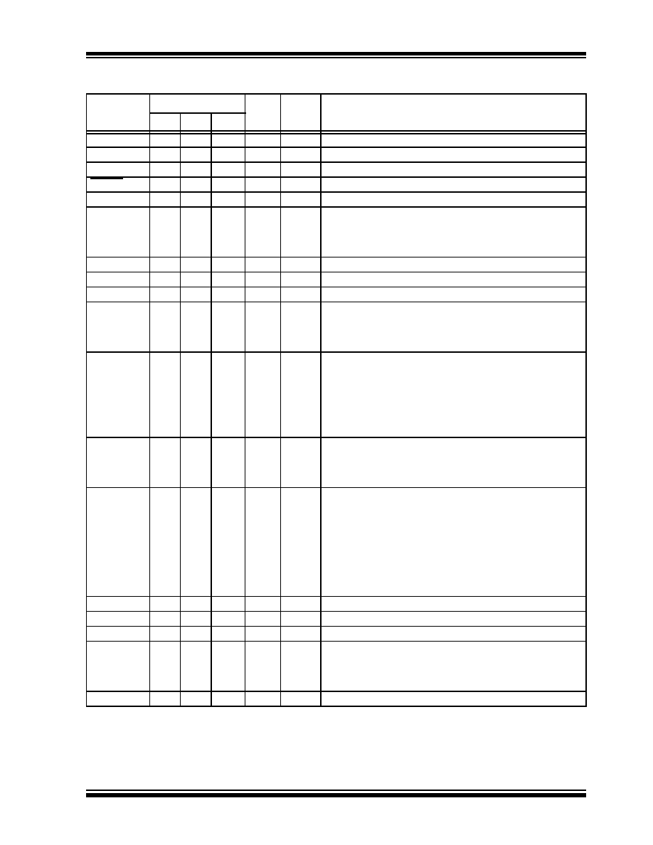
TABLE 1-2:
PIN DESCRIPTIONS
Pin Name
Pin Number
Pin
Type
Buffer
Type
Description
PDIP SOIC SSOP
BAUD0
1
I
ST
BAUD1:BAUD0 specify the baud rate of the device.
TXIR
2
O
—
Asynchronous transmit to Infrared transceiver.
RXIR
3
I
ST
Asynchronous receive from Infrared transceiver.
RESET
4
I
ST
Resets the device.
VSS
5
5, 6
—
P
Ground reference for logic and I/O pins.
EN
6
7
I
TTL
Device enable.
1
= Device is enabled.
0
= Device is disabled (low power). MCP2150 only monitors
this pin when in the NDM state.
TX
7
8
I
TTL
Asynchronous receive; from Host Controller UART.
RX
8
9
O
—
Asynchronous transmit; to Host Controller UART.
RI
9
10
—
Ring Indicator. The value on this pin is driven high.
DSR
10
11
O
—
Data Set Ready. Indicates that the MCP2150 has completed
reset.
1
= MCP2150 is initialized.
0
= MCP2150 is not initialized.
DTR
11
12
I
TTL
Data Terminal Ready. The value of this pin is ignored once
the MCP2150 is initialized. It is recommended that this pin be
connected so that the voltage level is either VSS or VCC. At
device power up, this signal is used with the RTS signal to
enter device ID programming.
1
= Enter Device ID programming mode (if RTS is cleared).
0
= Do not enter Device ID programming mode.
CTS
12
13
O
—
Clear to Send. Indicates that the MCP2150 is ready to
receive data from the Host Controller.
1
= Host Controller should not send data.
0
= Host Controller may send data.
RTS
13
14
I
TTL
Request to Send. Indicates that a Host Controller is ready to
receive data from the MCP2150. The MCP2150 prepares to
send data, if available.
1
= Host Controller not ready to receive data.
0
= Host Controller ready to receive data.
At device power up, this signal is used with the DTR signal to
enter device ID programming.
1
= Do not enter Device ID programming mode.
0
= Enter Device ID programming mode (if DTR is set).
VDD
14
15, 16
—
P
Positive supply for logic and I/O pins.
OSC2
15
17
O
—
Oscillator crystal output.
OSC1/CLKIN
16
18
I
CMOS Oscillator crystal input/external clock source input.
CD
17
19
O
—
Carrier Detect. Indicates that the MCP2150 has established a
valid link with a Primary Device.
1
= An IR link has not been established (No IR Link).
0
= An IR link has been established (IR Link).
BAUD1
18
20
I
ST
BAUD1:BAUD0 specify the baud rate of the device.
Legend:
TTL = TTL compatible input
I = Input
P = Power
ST = Schmitt Trigger input with CMOS levels
O = Output
CMOS = CMOS compatible input
相关PDF资料 |
PDF描述 |
|---|---|
| GBM10DRSN-S664 | CONN EDGECARD 20POS DIP .156 SLD |
| CB5278-000 | HEAT SHRINK TUBING |
| ELC-10D390E | COIL CHOKE 39UH RADIAL |
| CB5270-000 | HEAT SHRINK TUBING |
| VI-BWV-EX | CONVERTER MOD DC/DC 5.8V 75W |
相关代理商/技术参数 |
参数描述 |
|---|---|
| MCP2150-I/P | 功能描述:输入/输出控制器接口集成电路 IrDA protocol handlr RoHS:否 制造商:Silicon Labs 产品: 输入/输出端数量: 工作电源电压: 最大工作温度:+ 85 C 最小工作温度:- 40 C 安装风格:SMD/SMT 封装 / 箱体:QFN-64 封装:Tray |
| MCP2150-I/P | 制造商:Microchip Technology Inc 功能描述:IC IRDA CONTROLLER 2150 DIP18 |
| MCP2150-I/SO | 功能描述:输入/输出控制器接口集成电路 IrDA protocol handlr RoHS:否 制造商:Silicon Labs 产品: 输入/输出端数量: 工作电源电压: 最大工作温度:+ 85 C 最小工作温度:- 40 C 安装风格:SMD/SMT 封装 / 箱体:QFN-64 封装:Tray |
| MCP2150-I/SO | 制造商:Microchip Technology Inc 功能描述:IRDA CONTROLLER SMD 2150 SOIC18 |
| MCP2150-I/SORVB | 制造商:Microchip 功能描述:MCP2150 Series 115.2 kBaud 64 Byte Standard Protocol Stack Controller - SOIC-18 |
发布紧急采购,3分钟左右您将得到回复。