- 您现在的位置:买卖IC网 > PDF目录11718 > MCZ33889BEGR2 (Freescale Semiconductor)IC SYSTEM BASIS W/CAN 28-SOIC PDF资料下载
参数资料
| 型号: | MCZ33889BEGR2 |
| 厂商: | Freescale Semiconductor |
| 文件页数: | 13/59页 |
| 文件大小: | 0K |
| 描述: | IC SYSTEM BASIS W/CAN 28-SOIC |
| 标准包装: | 1,000 |
| 系列: | * |
| 应用: | * |
| 接口: | * |
| 电源电压: | * |
| 封装/外壳: | 28-SOIC(0.295",7.50mm 宽) |
| 供应商设备封装: | 28-SOIC W |
| 包装: | 带卷 (TR) |
| 安装类型: | 表面贴装 |
第1页第2页第3页第4页第5页第6页第7页第8页第9页第10页第11页第12页当前第13页第14页第15页第16页第17页第18页第19页第20页第21页第22页第23页第24页第25页第26页第27页第28页第29页第30页第31页第32页第33页第34页第35页第36页第37页第38页第39页第40页第41页第42页第43页第44页第45页第46页第47页第48页第49页第50页第51页第52页第53页第54页第55页第56页第57页第58页第59页
Analog Integrated Circuit Device Data
20
Freescale Semiconductor
33889
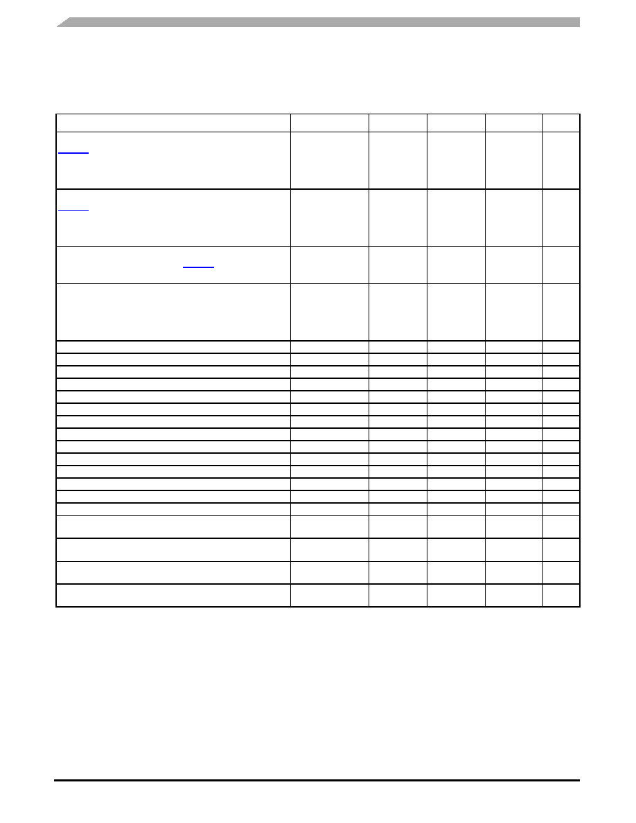
ELECTRICAL CHARACTERISTICS
DYNAMIC ELECTRICAL CHARACTERISTICS
Loop time Tx to Rx, no bus failure, MC33889D only ((27),
Figure 6) (ISO ICT test series 10)
Tx high to low transition (dominant edge)
Tx low to high transition (recessive edge)
tLOOPRD
-
1.15
1.45
1.5
s
Loop time Tx to Rx, with bus failure, MC33889D only ((27),
Figure 7) (ISO ICT test series 10)
Tx high to low transition (dominant edge)
Tx low to high transition (recessive edge)
tLOOPRD-F
-
1.9
s
Loop time Tx to Rx, with bus failure and
1.5 V gnd shift, 5
series 11)
tLOOPRD/DR-F+GS
3.6
s
Min. Dominant Time For Wake-up On CANL or CANH
(Term VBAT; VSUP = 12 V) Guaranteed by design.
MC33889B
MC33889D
tWAKE
-
8.0
30
16
-
30
s
Failure 3 Detection Time (Normal Mode)
tDF3
10
30
80
s
Failure 3 Recovery Time (Normal Mode)
tDR3
-
160
-
s
Failure 6 Detection Time (Normal Mode)
tDF6
50
200
500
s
Failure 6 Recovery Time (Normal Mode)
tDR6
150
200
1000
s
Failure 4, 7 Detection Time (Normal Mode)
tDF47
0.75
1.5
4.0
ms
Failure 4, 7 Recovery Time (Normal Mode)
tDR47
10
30
60
s
Failure 3a, 8 Detection Time (Normal Mode)
tDF8
0.75
1.7
4.0
ms
Failure 3a, 8 Recovery Time (Normal Mode)
tTDR8
0.75
1.5
4.0
ms
Failure 4, 7 Detection Time, (Term VBAT; VSUP = 12 V)
tDR47
0.8
1.2
8.0
ms
Failure 4, 7 Recovery Time (Term VBAT; VSUP = 12 V)
tDR47
-
1.92
-
ms
Failure 3 Detection Time (Term VBAT; VSUP = 12 V)
tDR3
-
3.84
-
ms
Failure 3 Recovery Time (Term VBAT; VSUP = 12 V)
tDR3
-
1.92
-
ms
Failure 3a, 8Detection Time (Term VBAT; VSUP = 12 V)
tDR8
-
2.3
-
ms
Failure 3a, 8 Recovery Time (Term VBAT; VSUP = 12 V)
tDR8
-
1.2
-
ms
Edge Count Difference Between CANH and CANL for Failures 1,
2, 5 Detection (Failure bit set, Normal Mode)
ECDF
-
3
-
Edge Count Difference Between CANH And CANL For Failures
1, 2, 5 Recovery (Normal Mode)
ECDR
-
3
-
TX Permanent Dominant Timer Disable Time
(Normal Mode And Failure Mode)
tTX,D
0.75
-
4.0
ms
TX Permanent Dominant Timer Enable Time
(Normal Mode And Failure Mode)
tTX,E
10
-
60
s
Notes
27.
AC characteristic according to ISO11898-3, tested per figure 5 and 6. Guaranteed by design, room temperature only.
28.
AC characteristic according to ISO11898-3, tested per figure 7. Max reported is the typical measurement under the worst condition (gnd
shift, dominant/recessive edge, at source or destination node. ref to ISO test specification). Guaranteed by design, room temperature
only.
Table 5. Dynamic Electrical Characteristics (continued)
VSUP From 5.5 V to 18 V, V2INT from 4.75 to 5.25 V and TJ from -40 to 150 °C, unless otherwise noted. Typical values noted
reflect the approximate parameter means at TA = 25°C under nominal conditions, unless otherwise noted.
Conditions
Symbol
Min
Typ
Max
Unit
相关PDF资料 |
PDF描述 |
|---|---|
| V150A24E500B2 | CONVERTER MOD DC/DC 24V 500W |
| D38999/24FE8SN | CONN RCPT 8POS JAM NUT W/SCKT |
| MCZ33889DEG | IC SYSTEM BASIS W/CAN 28-SOIC |
| V150A15E500BG2 | CONVERTER MOD DC/DC 15V 500W |
| MCZ33889DEGR2 | IC SYSTEM BASIS W/CAN 28-SOIC |
相关代理商/技术参数 |
参数描述 |
|---|---|
| MCZ33889DEG | 功能描述:网络控制器与处理器 IC SBC-LITE-LS-CAN RoHS:否 制造商:Micrel 产品:Controller Area Network (CAN) 收发器数量: 数据速率: 电源电流(最大值):595 mA 最大工作温度:+ 85 C 安装风格:SMD/SMT 封装 / 箱体:PBGA-400 封装:Tray |
| MCZ33889DEG | 制造商:Freescale Semiconductor 功能描述:IC SYSTEM BASIS W/CAN TRANCEIVER |
| MCZ33889DEG/R2 | 制造商:FREESCALE 制造商全称:Freescale Semiconductor, Inc 功能描述:System Basis Chip with Low Speed Fault Tolerant CAN Interface |
| MCZ33889DEGR2 | 功能描述:网络控制器与处理器 IC SBC-LITE-LS-CAN RoHS:否 制造商:Micrel 产品:Controller Area Network (CAN) 收发器数量: 数据速率: 电源电流(最大值):595 mA 最大工作温度:+ 85 C 安装风格:SMD/SMT 封装 / 箱体:PBGA-400 封装:Tray |
| MCZ33897AEF | 功能描述:网络控制器与处理器 IC SWCAN RoHS:否 制造商:Micrel 产品:Controller Area Network (CAN) 收发器数量: 数据速率: 电源电流(最大值):595 mA 最大工作温度:+ 85 C 安装风格:SMD/SMT 封装 / 箱体:PBGA-400 封装:Tray |
发布紧急采购,3分钟左右您将得到回复。