- 您现在的位置:买卖IC网 > PDF目录15211 > NCP5425DBG (ON Semiconductor)IC REG CTRLR BUCK PWM VM 20TSSOP PDF资料下载
参数资料
| 型号: | NCP5425DBG |
| 厂商: | ON Semiconductor |
| 文件页数: | 17/22页 |
| 文件大小: | 0K |
| 描述: | IC REG CTRLR BUCK PWM VM 20TSSOP |
| 标准包装: | 75 |
| PWM 型: | 电压模式 |
| 输出数: | 2 |
| 频率 - 最大: | 938kHz |
| 占空比: | 100% |
| 电源电压: | 4.75 V ~ 13.2 V |
| 降压: | 是 |
| 升压: | 无 |
| 回扫: | 无 |
| 反相: | 无 |
| 倍增器: | 无 |
| 除法器: | 无 |
| Cuk: | 无 |
| 隔离: | 无 |
| 工作温度: | 0°C ~ 125°C |
| 封装/外壳: | 20-TSSOP(0.173",4.40mm 宽) |
| 包装: | 管件 |
�� �
�
�NCP5425�
�RSENSE� +� 0.070� V�
�Control� IC� Power� Dissipation�
�The� power� dissipation� of� the� IC� varies� with� the� MOSFETs�
�used,� VCC,� and� the� NCP5425� operating� frequency.� The�
�average� MOSFET� gate� charge� current� typically� dominates�
�the� control� IC� power� dissipation,� and� is� given� by:�
�PCONTROL(IC)� +� ICC1VCC1� )� IBSTVBST�
�)� PGATE(H)1� )� PGATE(L)1�
�Sense� Resistor�
�A� sense� resistor� can� be� added� in� series� with� the� inductor.�
�When� the� voltage� drop� across� the� sense� resistor� exceeds� the�
�internal� voltage� threshold� of� 70� mV,� a� limit� condition� is� set.�
�The� sense� resistor� value� is� calculated� by:�
�ILIMIT�
�where:�
�)� PGATE(H)2� )� PGATE(L)2�
�In� a� high� current� supply,� the� sense� resistor� will� be� a� very�
�low� value,� typically� less� than� 10� m� W� .� Such� a� resistor� can� be�
�either� a� discrete� component� or� a� PCB� trace.� The� resistance�
�P� CONTROL(IC)� =� control� IC� power� dissipation;�
�I� CC1� =� IC� quiescent� supply� current;�
�V� CC1� =� IC� supply� voltage;�
�P� GATE(H)� =� upper� MOSFET� gate� driver� (IC)� losses;�
�P� GATE(L)� =� lower� MOSFET� gate� driver� (IC)� losses.�
�The� upper� (switching)� MOSFET� gate� driver� (IC)� losses�
�are� given� by:�
�of� a� discrete� component� can� be� more� precise� than� a� PCB�
�trace,� but� the� cost� is� also� greater.� Setting� the� current� limit�
�using� an� external� sense� resistor� is� very� precise� because� all�
�the� values� can� be� designed� to� specific� tolerances.� However,�
�the� disadvantage� of� using� a� sense� resistor� is� its� additional�
�constant� power� loss� and� heat� generation.� Trace� resistance�
�can� vary� as� much� as� "� 10%� due� to� copper� plating� variations.�
�PGATE(H)� +� QGATE(H)�
�fSW�
�VBST�
�Inductor� ESR�
�where:�
�P� GATE(H)� =� upper� MOSFET� gate� driver� (IC)� losses;�
�Q� GATE(H)� =� total� upper� MOSFET� gate� charge� at� VCC;�
�f� SW� =� switching� frequency.�
�The� lower� (synchronous)� MOSFET� gate� driver� (IC)�
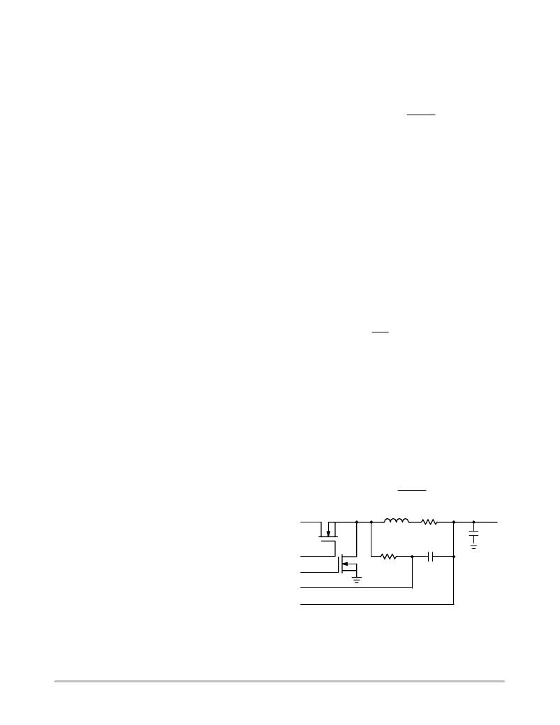
�Another� means� of� sensing� current� is� to� use� the� intrinsic�
�resistance� of� the� inductor.� A� model� of� an� inductor� reveals�
�that� the� windings� have� an� effective� series� resistance� (ESR).�
�The� voltage� drop� across� the� inductor� ESR� can� be� measured�
�with� a� simple� parallel� circuit:� an� RC� integrator.� If� the� value�
�of� RS1� and� C� are� chosen� such� that:�
�losses� are:�
�PGATE(L)� +� QGATE(L)�
�fSW�
�VCC�
�L�
�ESR�
�+� RS1C�
�RS1� +�
�ILIM� +� 0.070� V�
�where:�
�P� GATE(L)� =� lower� MOSFET� gate� driver� (IC)� losses;�
�Q� GATE(L)� =� total� lower� MOSFET� gate� charge� at� VCC;�
�f� SW� =� switching� frequency.�
�The� junction� temperature� of� the� control� IC� is� primarily� a�
�function� of� the� PCB� layout,� since� most� of� the� heat� is� removed�
�through� the� traces� connected� to� the� pins� of� the� IC.�
�CURRENT� SENSING� AND� CURRENT� SHARING�
�Current� Sharing� Errors�
�The� three� main� errors� in� current� are� from� board� layout�
�imbalances,� inductor� mismatch,� and� input� offsets� in� the� error�
�amplifiers.� The� first� two� sources� of� error� can� be� controlled�
�through� careful� component� selection� and� good� layout�
�then� the� voltage� measured� across� the� capacitor� C� will� be:�
�VC� +� ESR� ILIM�
�Inductor� Sensing� Component� Selection�
�Select� the� capacitor� C� first.� A� value� of� 0.1� m� F� is�
�recommended.� The� value� of� RS1� can� be� calculated� by:�
�L�
�ESR� C�
�Typical� values� for� inductor� ESR� range� in� the� low�
�milliohms;� consult� manufacturer� ’s� data� sheets� for� specific�
�values.� Selection� of� components� at� these� values� will� result�
�in� a� current� limit� of:�
�ESR�
�practice.� With� a� 4.0� m� W� (parasitic� winding� resistance)�
�inductor,� for� example,� one� mV� of� input� offset� error� will�
�represent� 0.25� A� of� measurement� error.� One� way� to� diminish�
�this� effect� is� to� use� higher� resistance� inductors,� but� the�
�penalty� is� higher� power� losses� in� the� inductors.�
�Current� Limiting� Options�
�The� current� supplied� to� the� load� can� be� sensed� using� the�
�IS+� and� IS?� pins.� These� pins� sense� a� voltage,� proportional�
�V� CC�
�GATE(H)�
�GATE(L)�
�IS+�
�IS?�
�L�
�RS1�
�ESR�
�C�
�Co�
�to� the� output� current,� and� compare� it� to� a� fixed� internal�
�voltage� threshold.� When� the� differential� voltage� exceeds�
�70� mV,� the� internal� overcurrent� protection� system� goes� into�
�a� cycle?by?cycle� limiting� mode.� Two� methods� for� sensing�
�the� current� are� available.�
�http://onsemi.com�
�17�
�Figure� 11.� Inductor� ESR� Current� Sensing�
�相关PDF资料 |
PDF描述 |
|---|---|
| CAT825RTDI-GT3 | IC SUPERVISOR MPU 2.63V TSOT23-5 |
| ISL6845IUZ-T | IC REG CTRLR BST FLYBK ISO 8MSOP |
| AGM06DRMH-S288 | CONN EDGECARD EXTEND 12POS .156 |
| ISL6845IRZ-T | IC REG CTRLR BST FLYBK ISO 8-DFN |
| VI-2TN-EY-F4 | CONVERTER MOD DC/DC 18.5V 50W |
相关代理商/技术参数 |
参数描述 |
|---|---|
| NCP5425DBR2 | 功能描述:DC/DC 开关控制器 Dual Synchronous RoHS:否 制造商:Texas Instruments 输入电压:6 V to 100 V 开关频率: 输出电压:1.215 V to 80 V 输出电流:3.5 A 输出端数量:1 最大工作温度:+ 125 C 安装风格: 封装 / 箱体:CPAK |
| NCP5425DBR2G | 功能描述:DC/DC 开关控制器 Dual Synchronous Buck RoHS:否 制造商:Texas Instruments 输入电压:6 V to 100 V 开关频率: 输出电压:1.215 V to 80 V 输出电流:3.5 A 输出端数量:1 最大工作温度:+ 125 C 安装风格: 封装 / 箱体:CPAK |
| NCP5425DOEVB | 功能描述:电源管理IC开发工具 ANA SW REG EVAL BRD RoHS:否 制造商:Maxim Integrated 产品:Evaluation Kits 类型:Battery Management 工具用于评估:MAX17710GB 输入电压: 输出电压:1.8 V |
| NCP5425S0EVB | 制造商:ON Semiconductor 功能描述: |
| NCP5425SOEVB | 功能描述:电源管理IC开发工具 ANA SW REG EVAL BRD RoHS:否 制造商:Maxim Integrated 产品:Evaluation Kits 类型:Battery Management 工具用于评估:MAX17710GB 输入电压: 输出电压:1.8 V |
发布紧急采购,3分钟左右您将得到回复。