- 您现在的位置:买卖IC网 > PDF目录367725 > P8xCL580HFT (NXP Semiconductors N.V.) Low voltage 8-bit microcontrollers with UART, I2C-bus and ADC PDF资料下载
参数资料
| 型号: | P8xCL580HFT |
| 厂商: | NXP Semiconductors N.V. |
| 英文描述: | Low voltage 8-bit microcontrollers with UART, I2C-bus and ADC |
| 中文描述: | 低电压8 - UART的,位微控制器的I2C总线和ADC |
| 文件页数: | 24/80页 |
| 文件大小: | 366K |
| 代理商: | P8XCL580HFT |
第1页第2页第3页第4页第5页第6页第7页第8页第9页第10页第11页第12页第13页第14页第15页第16页第17页第18页第19页第20页第21页第22页第23页当前第24页第25页第26页第27页第28页第29页第30页第31页第32页第33页第34页第35页第36页第37页第38页第39页第40页第41页第42页第43页第44页第45页第46页第47页第48页第49页第50页第51页第52页第53页第54页第55页第56页第57页第58页第59页第60页第61页第62页第63页第64页第65页第66页第67页第68页第69页第70页第71页第72页第73页第74页第75页第76页第77页第78页第79页第80页
1997 Mar 14
24
Philips Semiconductors
Product specification
Low voltage 8-bit microcontrollers with
UART, I
2
C-bus and ADC
P80CL580; P83CL580
13.1
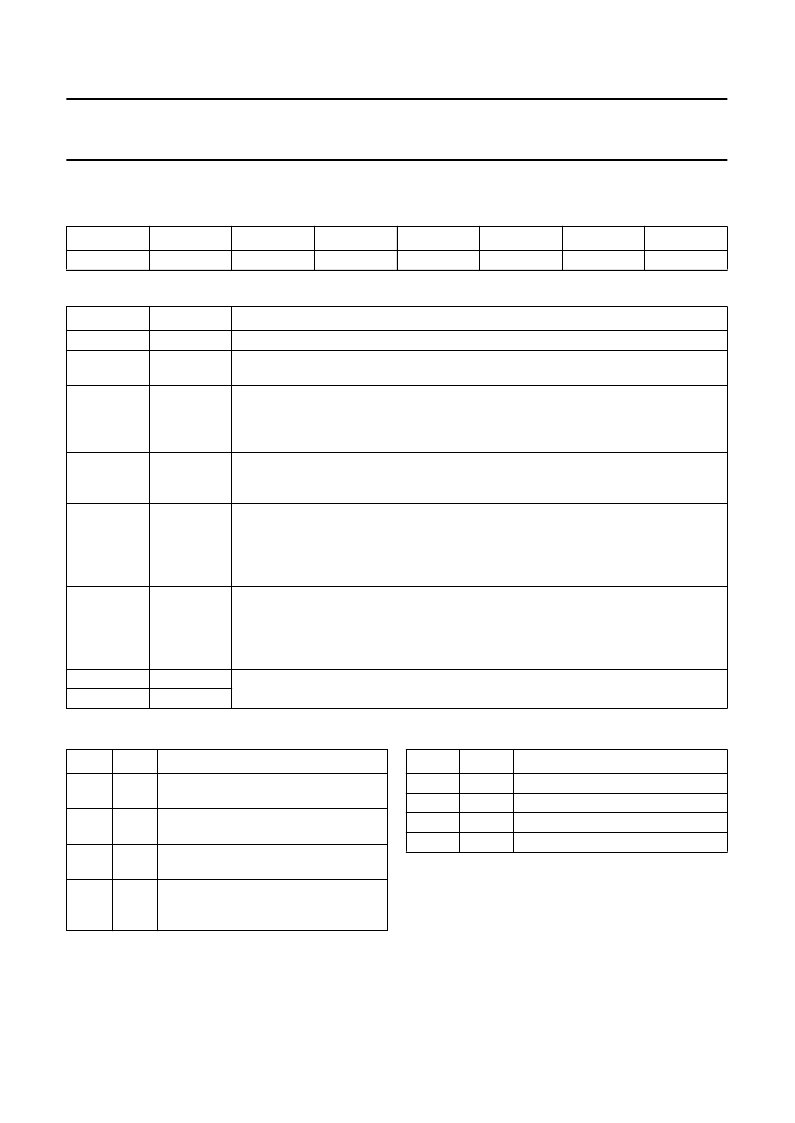
ADC Control Register (ADCON)
Table 9
ADC Control Register (address C4H)
Table 10
Description of ADCON bits
7
6
5
4
3
2
1
0
ADPD
ADEX
ADCI
ADCS
CKDIV
AADR1
AADR0
BIT
SYMBOL
ADPD
DESCRIPTION
7
6
Reserved.
Power-down.
This bit switches off the resistor reference to save power even when the
CPU is operating.
Enable external start of conversion
. This bit determines whether a conversion can be
started using the external pin STADC. When ADEX = 0, a conversion cannot be started
externally using STADC. When ADEX = 1, a conversion can be started externally using
STADC.
ADC interrupt flag
. This flag is set when an ADC conversion result is ready to be read.
An interrupt is invoked if this is enabled. This flag must be cleared by software (it cannot
be set by software); see Table 11.
ADC start and status flag
. When this bit is set an ADC conversion is started. ADCS
may be set by software or by the external signal STADC. The ADC logic ensures that
this signal is HIGH while the ADC is busy. On completion of the conversion ADCS is
reset and after that the interrupt flag ADCI is set. ADCS cannot be reset by software;
see Table 11.
This bit selects the conversion time, in terms of instruction cycles. This allows the CPU
to be run at the maximum frequency (12 MHz) yet keeping the ADC timing at low
frequency. When CKDIV = 0, the conversion time is equivalent to 24 instruction cycles.
When CKDIV = 1, the conversion time is equivalent to 48 instruction cycles.
The conversion time includes a sampling time of 6 cycles.
Analog input select
. These bits are used to select one of the four analog inputs; see
Table 12. They only can be changed when ADCI and ADCS are both LOW.
5
ADEX
4
ADCI
3
ADCS
2
CKDIV
1
0
AADR1
AADR0
Table 11
Analog-to-digital operation
ADCI
ADCS
OPERATION
0
0
ADC not busy; a conversion can be
started.
ADC busy; start of a new conversion is
blocked.
Conversion completed; start of a new
conversion is blocked.
Intermediate status for a maximum of
one machine cycle before conversion is
completed (ADCI = 1, ADCS = 0).
0
1
1
0
1
1
Table 12
Selection of analog input channel
AADR1 AADR0
SELECTED CHANNEL
0
0
1
1
0
1
0
1
AD0
AD1
AD2
AD3
相关PDF资料 |
PDF描述 |
|---|---|
| P8216 | Four-Bit Parallel Bidirectional Bus Driver |
| P8226 | Four-Bit Parallel Bidirectional Bus Driver |
| P82284-6 | CPU System Clock Generator |
| D82284-6 | CPU System Clock Generator |
| D82284-6B | CPU System Clock Generator |
相关代理商/技术参数 |
参数描述 |
|---|---|
| P8Z77 DELUXE | 制造商:Asus 功能描述:P8Z77-V Deluxe ATX Motherboard |
| P8Z77 M PRO | 制造商:Asus 功能描述:P8Z77-M Pro MicroATX Motherboard |
| P8Z77 V | 制造商:Asus 功能描述:P8Z77-V ATX Motherboard |
| P8Z77 V PRO | 制造商:Asus 功能描述:P8Z77-V Pro ATX Motherboard |
| P8Z77-V | 制造商:ASUSTeK Computer Inc 功能描述:P8Z77-V ATX Motherboard |
发布紧急采购,3分钟左右您将得到回复。