- 您现在的位置:买卖IC网 > PDF目录367725 > P8xCL580HFT (NXP Semiconductors N.V.) Low voltage 8-bit microcontrollers with UART, I2C-bus and ADC PDF资料下载
参数资料
| 型号: | P8xCL580HFT |
| 厂商: | NXP Semiconductors N.V. |
| 英文描述: | Low voltage 8-bit microcontrollers with UART, I2C-bus and ADC |
| 中文描述: | 低电压8 - UART的,位微控制器的I2C总线和ADC |
| 文件页数: | 66/80页 |
| 文件大小: | 366K |
| 代理商: | P8XCL580HFT |
第1页第2页第3页第4页第5页第6页第7页第8页第9页第10页第11页第12页第13页第14页第15页第16页第17页第18页第19页第20页第21页第22页第23页第24页第25页第26页第27页第28页第29页第30页第31页第32页第33页第34页第35页第36页第37页第38页第39页第40页第41页第42页第43页第44页第45页第46页第47页第48页第49页第50页第51页第52页第53页第54页第55页第56页第57页第58页第59页第60页第61页第62页第63页第64页第65页当前第66页第67页第68页第69页第70页第71页第72页第73页第74页第75页第76页第77页第78页第79页第80页
1997 Mar 14
66
Philips Semiconductors
Product specification
Low voltage 8-bit microcontrollers with
UART, I
2
C-bus and ADC
P80CL580; P83CL580
Notes to the DC characteristics
1.
Capacitive loading on Ports 0 and 2 may cause spurious noise pulses to be superimposed on the LOW level output
voltage of ALE, Port 1 and Port 3 pins when these make a HIGH-to-LOW transition during bus operations. The noise
is due to external bus capacitance discharging into the Port 0 and Port 2 pins when these pins make HIGH-to-LOW
transitions during bus operations. In the most adverse conditions (capacitive loading
>
100 pF), the noise pulse on
the ALE line may exceed 0.8 V. In such events it may be required to qualify ALE with a Schmitt trigger, or use an
address latch with a Schmitt trigger strobe input.
2.
Capacitive loading on Ports 0 and 2 may cause the HIGH level output voltage on ALE and PSEN to momentarily fall
below the 0.9V
DD
specification when the address bits are stabilizing.
3.
The operating supply current is measured with all output pins disconnected; XTAL1 driven with t
r
= t
f
= 10 ns;
V
IL
= V
SS
; V
IH
= V
DD
; XTAL2 not connected; EA = RST = Port 0 = V
DD
.
4.
The Idle mode supply current is measured with all output pins disconnected; XTAL1 driven with t
r
= t
f
= 10 ns;
V
IL
= V
SS
; V
IH
= V
DD
; XTAL2 not connected; EA = Port 0 = V
DD
.
5.
The power-down current is measured with all output pins disconnected; XTAL1 not connected; EA = Port 0 = V
DD
;
RST = V
SS
.
6.
The input threshold voltage of P1.6/SCL and P1.7/SDA meet the I
2
C-bus specification. Therefore, an input voltage
below 0.3V
DD
will be recognized as a logic 0 and an input voltage above 0.7V
DD
will be recognized as a logic 1.
7.
V
DD
= 2.7 to 6 V; V
SS
= 0 V; V
SSA
= 0 V; V
ref(p)(A)
= V
DD
; T
amb
=
40 to +85
°
C, unless otherwise specified.
f
xtal(min)
= 250 kHz.
8.
Absolute error: the maximum difference between actual and ideal code transitions. Absolute error accounts for all
deviations of an actual converter from an ideal converter.
9.
Zero-offset error: the difference between the actual and ideal input voltage corresponding to the first actual code
transition.
10. Differential non-linearity: the difference between the actual and ideal code widths.
11. Channel-to-channel matching: the difference between corresponding code transitions of actual characteristics taken
from different channels under the same temperature, voltage and frequency conditions. Not tested, but verified on
sampling basis.
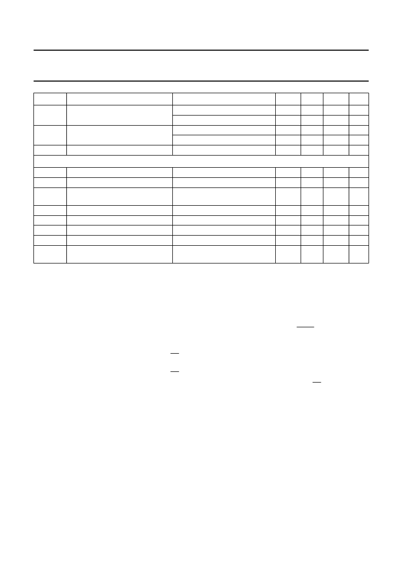
I
IL
input current logic 0
V
DD
= 5 V; V
IN
= 0.4 V
V
DD
= 2.5 V; V
IN
= 0.4 V
V
DD
= 5 V; V
IN
= 0.5V
DD
V
DD
= 2.5 V; V
IN
= 0.5V
DD
10
100
50
1.0
500
200
μ
A
μ
A
mA
μ
A
k
I
ITL
input current logic 0; HIGH-to-LOW
transition
R
RST
RST pull-down resistor
Analog inputs
(note 7)
V
IN(A)
V
ref(p)(A)
R
ref
analog input voltage
reference voltage
resistance between
V
ref(p)(A)
and V
SSA
analog on-chip input capacitance
absolute error (note 8)
zero-offset error (note 9)
differential non-linearity (note 10)
channel-to-channel matching
(note 11)
V
SSA
2.7
25
V
DD
V
DD
100
mA
mA
k
C
AIN
A
e
OS
e
DL
e
M
ctc
3
±
1
±
1
±
1
±
1
2
pF
LSB
LSB
LSB
LSB
SYMBOL
PARAMETER
CONDITIONS
MIN.
TYP.
MAX.
UNIT
相关PDF资料 |
PDF描述 |
|---|---|
| P8216 | Four-Bit Parallel Bidirectional Bus Driver |
| P8226 | Four-Bit Parallel Bidirectional Bus Driver |
| P82284-6 | CPU System Clock Generator |
| D82284-6 | CPU System Clock Generator |
| D82284-6B | CPU System Clock Generator |
相关代理商/技术参数 |
参数描述 |
|---|---|
| P8Z77 DELUXE | 制造商:Asus 功能描述:P8Z77-V Deluxe ATX Motherboard |
| P8Z77 M PRO | 制造商:Asus 功能描述:P8Z77-M Pro MicroATX Motherboard |
| P8Z77 V | 制造商:Asus 功能描述:P8Z77-V ATX Motherboard |
| P8Z77 V PRO | 制造商:Asus 功能描述:P8Z77-V Pro ATX Motherboard |
| P8Z77-V | 制造商:ASUSTeK Computer Inc 功能描述:P8Z77-V ATX Motherboard |
发布紧急采购,3分钟左右您将得到回复。