- 您现在的位置:买卖IC网 > PDF目录11641 > PIC10F222-I/OT (Microchip Technology)IC PIC MCU FLASH 512X12 SOT-23-6 PDF资料下载
参数资料
| 型号: | PIC10F222-I/OT |
| 厂商: | Microchip Technology |
| 文件页数: | 31/86页 |
| 文件大小: | 0K |
| 描述: | IC PIC MCU FLASH 512X12 SOT-23-6 |
| 标准包装: | 3,000 |
| 系列: | PIC® 10F |
| 核心处理器: | PIC |
| 芯体尺寸: | 8-位 |
| 速度: | 8MHz |
| 外围设备: | POR,WDT |
| 输入/输出数: | 4 |
| 程序存储器容量: | 768B(512 x 12) |
| 程序存储器类型: | 闪存 |
| RAM 容量: | 23 x 8 |
| 电压 - 电源 (Vcc/Vdd): | 2 V ~ 5.5 V |
| 数据转换器: | A/D 2x8b |
| 振荡器型: | 内部 |
| 工作温度: | -40°C ~ 85°C |
| 封装/外壳: | SOT-23-6 |
| 包装: | 散装 |
第1页第2页第3页第4页第5页第6页第7页第8页第9页第10页第11页第12页第13页第14页第15页第16页第17页第18页第19页第20页第21页第22页第23页第24页第25页第26页第27页第28页第29页第30页当前第31页第32页第33页第34页第35页第36页第37页第38页第39页第40页第41页第42页第43页第44页第45页第46页第47页第48页第49页第50页第51页第52页第53页第54页第55页第56页第57页第58页第59页第60页第61页第62页第63页第64页第65页第66页第67页第68页第69页第70页第71页第72页第73页第74页第75页第76页第77页第78页第79页第80页第81页第82页第83页第84页第85页第86页
2007 Microchip Technology Inc.
DS41270E-page 35
PIC10F220/222
TABLE 8-2:
RESET CONDITION FOR SPECIAL REGISTERS
8.3.1
MCLR ENABLE
This Configuration bit, when unprogrammed (left in the
‘1’ state), enables the external MCLR function. When
programmed, the MCLR function is tied to the internal
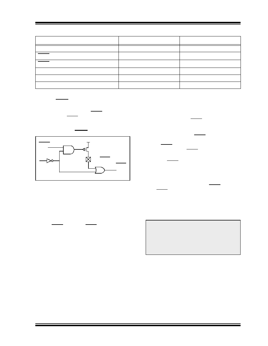
FIGURE 8-1:
MCLR SELECT
8.4
Power-on Reset (POR)
The PIC10F220/222 devices incorporate an on-chip
Power-on Reset (POR) circuitry, which provides an
internal chip Reset for most power-up situations.
The on-chip POR circuit holds the chip in Reset until
VDD has reached a high enough level for proper oper-
ation. To take advantage of the internal POR, program
the GP3/MCLR/VPP pin as MCLR and tie through a
resistor to VDD, or program the pin as GP3. An internal
weak pull-up resistor is implemented using a transistor
(refer to Table 10-1 for the pull-up resistor ranges). This
will eliminate external RC components usually needed
to create a Power-on Reset.
When the devices start normal operation (exit the
Reset condition), device operating parameters (volt-
age, frequency, temperature,...) must be met to ensure
operation. If these conditions are not met, the devices
must be held in Reset until the operating parameters
are met.
A simplified block diagram of the on-chip Power-on
Reset circuit is shown in Figure 8-2.
The Power-on Reset circuit and the Device Reset
Timer (see Section 8.5 “Device Reset Timer (DRT)”)
circuit are closely related. On power-up, the Reset latch
is set and the DRT is reset. The DRT timer begins
counting once it detects MCLR to be high. After the
time-out period, which is typically 1.125 ms, it will reset
the Reset latch and thus end the on-chip Reset signal.
A power-up example where MCLR is held low is shown
bringing MCLR high. The chip will actually come out of
Reset TDRT msec after MCLR goes high.
In Figure 8-4, the on-chip Power-on Reset feature is
being used (MCLR and VDD are tied together or the pin
is programmed to be GP3). The VDD is stable before
the Start-up timer times out and there is no problem in
getting a proper Reset. However, Figure 8-5 depicts a
problem situation where VDD rises too slowly. The time
between when the DRT senses that MCLR is high and
when MCLR and VDD actually reach their full value, is
too long. In this situation, when the start-up timer times
out, VDD has not reached the VDD (min) value and the
chip may not function correctly. For such situations, we
recommend that external RC circuits be used to
achieve longer POR delay times (Figure 8-4).
For additional information on design considerations
related to the use of PIC10F220/222 devices with their
short device Reset timer, refer to Application Notes
AN522, “Power-Up Considerations” (DS00522) and
AN607, “Power-up Trouble Shooting” (DS00607).
STATUS Addr: 03h
PCL Addr: 02h
Power-on Reset
0--1 1xxx
1111 1111
MCLR Reset during normal operation
0--u uuuu
1111 1111
MCLR Reset during Sleep
0--1 0uuu
1111 1111
WDT Reset during Sleep
0--0 0uuu
1111 1111
WDT Reset normal operation
0--0 uuuu
1111 1111
Wake-up from Sleep on pin change
1--1 0uuu
1111 1111
Legend: u = unchanged, x = unknown, – = unimplemented bit, read as ‘0’.
GP3/MCLR/VPP
MCLRE
Internal MCLR
GPWU
Weak Pull-up
Note:
When the devices start normal operation
(exit the Reset condition), device operat-
ing parameters (voltage, frequency, tem-
perature, etc.) must be met to ensure
proper operation. If these conditions are
not met, the device must be held in Reset
until the operating conditions are met.
相关PDF资料 |
PDF描述 |
|---|---|
| VE-J6P-IY-F4 | CONVERTER MOD DC/DC 13.8V 50W |
| PIC10F220-E/OT | IC PIC MCU FLASH 256X12 SOT-23-6 |
| VE-J6P-IY-F3 | CONVERTER MOD DC/DC 13.8V 50W |
| PIC10F200T-I/MC | IC PIC MCU FLASH 256X12 8DFN |
| VE-J6N-IY-F1 | CONVERTER MOD DC/DC 18.5V 50W |
相关代理商/技术参数 |
参数描述 |
|---|---|
| PIC10F222IP | 制造商:MICROCHIP 制造商全称:Microchip Technology 功能描述:6-Pin, 8-Bit Flash Microcontrollers |
| PIC10F222TE/MC | 制造商:MICROCHIP 制造商全称:Microchip Technology 功能描述:High-Performance Microcontrollers with 8-bit A/D |
| PIC10F222TE/OT | 制造商:MICROCHIP 制造商全称:Microchip Technology 功能描述:High-Performance Microcontrollers with 8-bit A/D |
| PIC10F222T-E/OT | 功能描述:8位微控制器 -MCU 768 B FL 16 RAM RoHS:否 制造商:Silicon Labs 核心:8051 处理器系列:C8051F39x 数据总线宽度:8 bit 最大时钟频率:50 MHz 程序存储器大小:16 KB 数据 RAM 大小:1 KB 片上 ADC:Yes 工作电源电压:1.8 V to 3.6 V 工作温度范围:- 40 C to + 105 C 封装 / 箱体:QFN-20 安装风格:SMD/SMT |
| PIC10F222T-E/OT-CUT TAPE | 制造商:Microchip 功能描述:PIC10 Series 23 B RAM 0.75 KB Flash 8-Bit Flash Microcontroller - SOT-23-6 |
发布紧急采购,3分钟左右您将得到回复。