- 您现在的位置:买卖IC网 > PDF目录11590 > PIC16F676-E/P (Microchip Technology)IC MCU FLASH 1KX14 W/AD 14DIP PDF资料下载
参数资料
| 型号: | PIC16F676-E/P |
| 厂商: | Microchip Technology |
| 文件页数: | 102/132页 |
| 文件大小: | 0K |
| 描述: | IC MCU FLASH 1KX14 W/AD 14DIP |
| 产品培训模块: | Asynchronous Stimulus |
| 标准包装: | 30 |
| 系列: | PIC® 16F |
| 核心处理器: | PIC |
| 芯体尺寸: | 8-位 |
| 速度: | 20MHz |
| 外围设备: | 欠压检测/复位,POR,WDT |
| 输入/输出数: | 12 |
| 程序存储器容量: | 1.75KB(1K x 14) |
| 程序存储器类型: | 闪存 |
| EEPROM 大小: | 128 x 8 |
| RAM 容量: | 64 x 8 |
| 电压 - 电源 (Vcc/Vdd): | 2 V ~ 5.5 V |
| 数据转换器: | A/D 8x10b |
| 振荡器型: | 内部 |
| 工作温度: | -40°C ~ 125°C |
| 封装/外壳: | 14-DIP(0.300",7.62mm) |
| 包装: | 管件 |
| 配用: | DM163029-ND - BOARD PICDEM FOR MECHATRONICS |
第1页第2页第3页第4页第5页第6页第7页第8页第9页第10页第11页第12页第13页第14页第15页第16页第17页第18页第19页第20页第21页第22页第23页第24页第25页第26页第27页第28页第29页第30页第31页第32页第33页第34页第35页第36页第37页第38页第39页第40页第41页第42页第43页第44页第45页第46页第47页第48页第49页第50页第51页第52页第53页第54页第55页第56页第57页第58页第59页第60页第61页第62页第63页第64页第65页第66页第67页第68页第69页第70页第71页第72页第73页第74页第75页第76页第77页第78页第79页第80页第81页第82页第83页第84页第85页第86页第87页第88页第89页第90页第91页第92页第93页第94页第95页第96页第97页第98页第99页第100页第101页当前第102页第103页第104页第105页第106页第107页第108页第109页第110页第111页第112页第113页第114页第115页第116页第117页第118页第119页第120页第121页第122页第123页第124页第125页第126页第127页第128页第129页第130页第131页第132页
2010 Microchip Technology Inc.
DS40039F-page 71
PIC16F630/676
9.8
Code Protection
If the code protection bit(s) have not been
programmed, the on-chip program memory can be
read out for verification purposes.
9.9
ID Locations
Four memory locations (2000h-2003h) are designated
as ID locations where the user can store checksum or
other code identification numbers. These locations are
not accessible during normal execution but are
readable and writable during Program/Verify. Only the
Least Significant 7 bits of the ID locations are used.
9.10
In-Circuit Serial Programming
The PIC16F630/676 microcontrollers can be serially
programmed while in the end application circuit. This is
simply done with two lines for clock and data, and three
other lines for:
power
ground
programming voltage
This allows customers to manufacture boards with
unprogrammed devices and then program the micro-
controller just before shipping the product. This also
allows the most recent firmware or a custom firmware
to be programmed.
The device is placed into a Program/Verify mode by
holding the RA0 and RA1 pins low, while raising the
MCLR (VPP) pin from VIL to VIHH (see Programming
Specification). RA0 becomes the programming data
and RA1 becomes the programming clock. Both RA0
and RA1 are Schmitt Trigger inputs in this mode.
After Reset, to place the device into Programming/Ver-
ify mode, the program counter (PC) is at location 00h.
A 6-bit command is then supplied to the device.
Depending on the command, 14 bits of program data
are then supplied to or from the device, depending on
whether the command was a load or a read. For
complete details of serial programming, please refer to
the PIC16F630/676 Programming Specification.
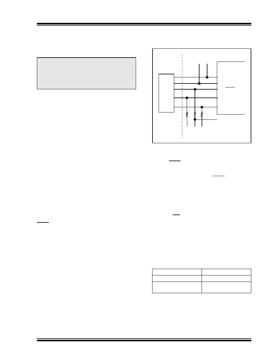
A typical In-Circuit Serial Programming connection is
shown in Figure 9-14.
FIGURE 9-14:
TYPICAL IN-CIRCUIT
SERIAL PROGRAMMING
CONNECTION
9.11
In-Circuit Debugger
Since in-circuit debugging requires the loss of clock,
data and MCLR pins, MPLAB ICD 2 development with
an 14-pin device is not practical. A special 20-pin
PIC16F676-ICD device is used with MPLAB ICD 2 to
provide separate clock, data and MCLR pins and frees
all normally available pins to the user.
This special ICD device is mounted on the top of the
header and its signals are routed to the MPLAB ICD 2
connector. On the bottom of the header is an 14-pin
socket that plugs into the user’s target via the 14-pin
stand-off connector.
When the ICD pin on the PIC16F676-ICD device is
held low, the In-Circuit Debugger functionality is
enabled. This function allows simple debugging
functions when used with MPLAB ICD 2. When the
microcontroller has this feature enabled, some of the
resources are not available for general use. Table 9-10
shows which features are consumed by the
background debugger:
TABLE 9-10:
DEBUGGER RESOURCES
For more information, see 14-Pin MPLAB ICD 2
Header Information Sheet (DS51292) available on
Microchip’s web site (www.microchip.com).
Note:
The entire data EEPROM and Flash
program memory will be erased when the
code protection is turned off. The INTOSC
calibration data is also erased. See
PIC16F630/676 Programming Specifica-
tion for more information.
I/O pins
ICDCLK, ICDDATA
Stack
1 level
Program Memory
Address 0h must be NOP
300h-3FEh
External
Connector
Signals
To Normal
Connections
To Normal
Connections
PIC16F630/676
VDD
VSS
RA3/MCLR/VPP
RA1
RA0
+5V
0V
VPP
CLK
Data I/O
VDD
相关PDF资料 |
PDF描述 |
|---|---|
| PIC12LCE518-04/SN | IC MCU OTP 512X12 LV W/EE 8SOIC |
| PIC12CE518-04I/SM | IC MCU OTP 512X12 W/EE 8-SOIC |
| PIC16LF1829T-I/ML | MCU PIC 14KB FLASH 20-QFN |
| PIC16F1829T-I/ML | MCU PIC 14K FLASH 1K RAM 20QFN |
| PIC16F716-E/ML | IC PIC MCU FLASH 2KX14 28QFN |
相关代理商/技术参数 |
参数描述 |
|---|---|
| PIC16F676-I/ML | 功能描述:8位微控制器 -MCU 1.75 KB 64 RAM 12I/O RoHS:否 制造商:Silicon Labs 核心:8051 处理器系列:C8051F39x 数据总线宽度:8 bit 最大时钟频率:50 MHz 程序存储器大小:16 KB 数据 RAM 大小:1 KB 片上 ADC:Yes 工作电源电压:1.8 V to 3.6 V 工作温度范围:- 40 C to + 105 C 封装 / 箱体:QFN-20 安装风格:SMD/SMT |
| PIC16F676-I/P | 功能描述:8位微控制器 -MCU 1.75KB 64 RAM 12 I/O Ind Temp PDIP14 RoHS:否 制造商:Silicon Labs 核心:8051 处理器系列:C8051F39x 数据总线宽度:8 bit 最大时钟频率:50 MHz 程序存储器大小:16 KB 数据 RAM 大小:1 KB 片上 ADC:Yes 工作电源电压:1.8 V to 3.6 V 工作温度范围:- 40 C to + 105 C 封装 / 箱体:QFN-20 安装风格:SMD/SMT |
| PIC16F676-I/P | 制造商:Microchip Technology Inc 功能描述:IC 8BIT FLASH MCU 16F676 DIP14 |
| PIC16F676-I/SL | 功能描述:8位微控制器 -MCU 1.75KB 64 RAM 12 I/O Ind Temp SOIC14 RoHS:否 制造商:Silicon Labs 核心:8051 处理器系列:C8051F39x 数据总线宽度:8 bit 最大时钟频率:50 MHz 程序存储器大小:16 KB 数据 RAM 大小:1 KB 片上 ADC:Yes 工作电源电压:1.8 V to 3.6 V 工作温度范围:- 40 C to + 105 C 封装 / 箱体:QFN-20 安装风格:SMD/SMT |
| PIC16F676-I/SL | 制造商:Microchip Technology Inc 功能描述:8BIT FLASH MCU SMD 16F676 SOIC14 |
发布紧急采购,3分钟左右您将得到回复。