参数资料
| 型号: | ISL6314IRZ-T |
| 厂商: | Intersil |
| 文件页数: | 10/32页 |
| 文件大小: | 0K |
| 描述: | IC CTRLR PWM 1PHASE BUCK 32-QFN |
| 产品培训模块: | Solutions for Industrial Control Applications |
| 标准包装: | 6,000 |
| 应用: | 控制器,Intel VR11,AMD CPU |
| 输入电压: | 5 V ~ 12 V |
| 输出数: | 1 |
| 输出电压: | 0.38 V ~ 1.6 V |
| 工作温度: | -40°C ~ 85°C |
| 安装类型: | 表面贴装 |
| 封装/外壳: | 32-VFQFN 裸露焊盘 |
| 供应商设备封装: | 32-QFN 裸露焊盘(5x5) |
| 包装: | 带卷 (TR) |
第1页第2页第3页第4页第5页第6页第7页第8页第9页当前第10页第11页第12页第13页第14页第15页第16页第17页第18页第19页第20页第21页第22页第23页第24页第25页第26页第27页第28页第29页第30页第31页第32页
�� �
�
�ISL6314�
�(� V� IN� –� V� OUT� )� ?� V� OUT� (EQ.� 1)�
�L� ?� f� S� ?� V�
�PHASE� (Pin� 24)�
�Connect� this� pin� to� the� source� of� the� upper� MOSFET.� This�
�pin� is� the� return� path� for� the� upper� MOSFET� drive.�
�LGATE� (Pin� 21)�
�This� pin� is� used� to� control� the� lower� MOSFET.� Connect� this�
�pin� to� the� lower� MOSFET� gate.�
�SS� (Pin� 2)�
�A� resistor,� R� SS� ,� placed� from� SS� to� VCC� or� GND� will� set� the�
�soft-start� ramp� slope.� Refer� to� Equations� 16� and� 17� for�
�proper� resistor� calculation.�
�The� state� of� the� SS� pin� also� selects� which� of� the� available� DAC�
�tables� will� be� used� to� decode� the� VID� inputs� and� puts� the�
�controller� into� the� corresponding� mode� of� operation.� For� Intel�
�VR11� mode� of� operation� the� R� SS� resistor� should� be� tied� to�
�GND.� AMD� compliance� is� selected� if� the� R� SS� resistor� is� tied� to�
�VCC� (once� in� AMD� mode,� the� VID7� bit� selects� 5-bit� DAC� if� set�
�to� a� logic� high,� or� 6-bit� DAC� if� set� to� a� logic� low).�
�PGOOD� (Pin� 1)�
�For� Intel� mode� of� operation,� PGOOD� indicates� whether� VSEN�
�is� within� specified� overvoltage� and� undervoltage� limits� after� a�
�fixed� delay� from� the� end� of� soft-start.� If� VSEN� exceeds� these�
�limits,� or� if� an� overcurrent� event� occurs,� or� if� the� part� is�
�disabled,� PGOOD� is� pulled� low.� PGOOD� is� always� low� prior� to�
�the� end� of� soft-start.�
�For� AMD� modes� of� operation,� PGOOD� will� always� be� high� as�
�long� as� VSEN� is� within� the� specified� undervoltage/overvoltage�
�window� and� soft-start� has� ended.� PGOOD� only� goes� low� if�
�VSEN� is� outside� this� window.�
�ISENO,� ISEN-,� and� ISEN+� (Pins� 14,� 15,� 16)�
�ISEN-,� ISEN+,� and� ISENO� are� the� DCR� current� sense�
�amplifier’s� negative� input,� positive� input,� and� output�
�respectively.� For� accurate� DCR� current� sensing,� connect� a�
�resistor� from� the� phase� node� to� ISEN-� and� connect� ISEN+� to�
�the� output� inductor,� roughly� VOUT.� A� parallel� R-C� feedback�
�circuit� connected� between� ISEN-� and� ISENO� will� then� create�
�a� voltage� from� ISEN+� to� ISENO� proportional� to� the� voltage�
�drop� across� the� inductor� DCR.� This� voltage� is� referred� to� as�
�the� droop� voltage� and� is� added� to� the� differential�
�remote-sense� amplifier’s� output.�
�An� optional� 0.001μF� to� 0.01μF� ceramic� capacitor� can� be�
�placed� from� the� ISEN+� pin� to� the� ISEN-� pin� to� help� reduce�
�common� mode� noise� that� might� be� introduced� by� the� layout.�
�Operation�
�Power� Conversion�
�The� ISL6314� controller� helps� simplify� implementation� by�
�integrating� vital� functions� and� requiring� minimal� external�
�components.� The� “Block� Diagram”� on� page� 3� provides� a� top�
�level� view� of� the� single-phase� power� conversion� using� the�
�ISL6314� controller.�
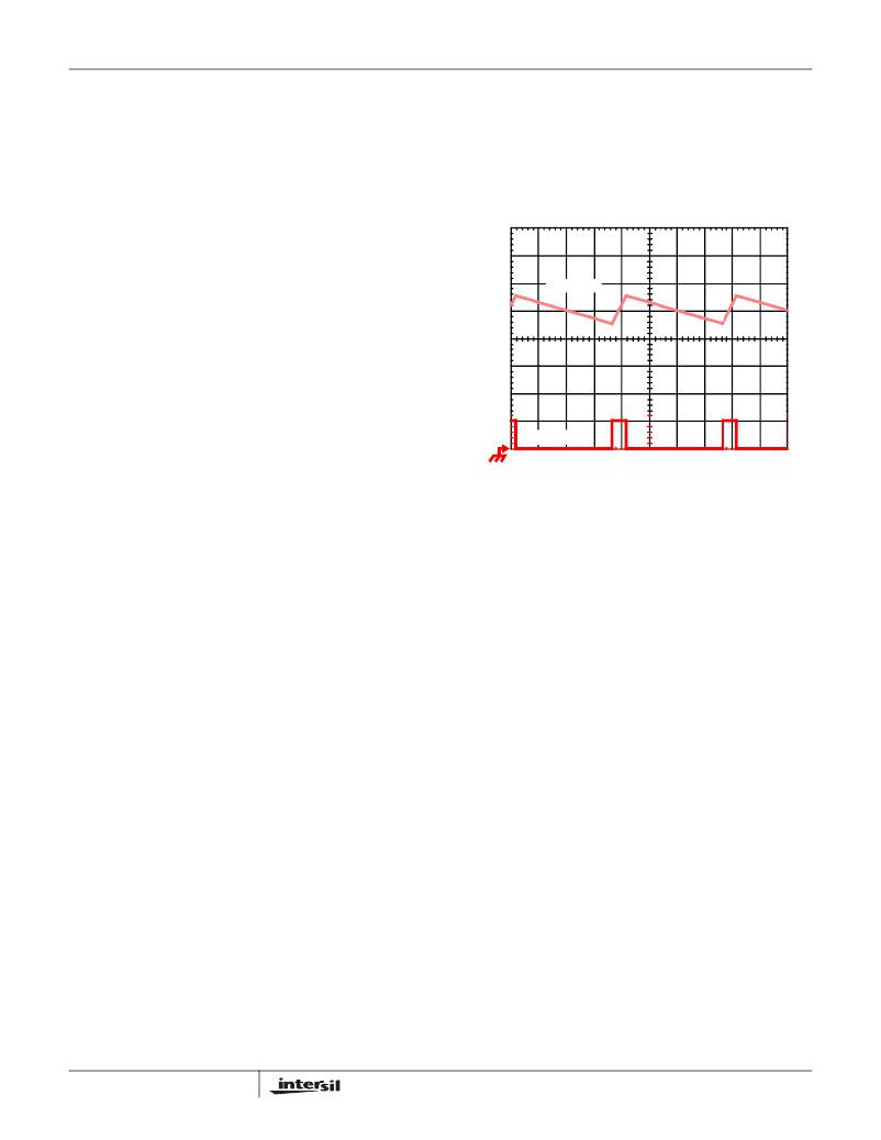
�IL,� 7A/DIV�
�PWM,� 5V/DIV�
�1μs/DIV�
�FIGURE� 1.� PWM� AND� INDUCTOR-CURRENT� WAVEFORMS�
�FOR� 1-PHASE� CONVERTER�
�Output� Ripple�
�Figure� 1� illustrates� the� output� ripple.� The� PWM� current� forms�
�the� AC� ripple� current� and� the� DC� load� current.� The�
�peak-to-peak� current� about� 7A,� and� the� DC� components� of�
�the� inductor� current� feeds� the� load.�
�To� understand� the� ripple� current� amplitude,� examine�
�Equation� 1� representing� a� single� channel� peak-to-peak�
�inductor� current.�
�I� P-P� =� ----------------------------------------------------------�
�IN�
�In� Equation� 1,� V� IN� and� V� OUT� are� the� input� and� output�
�voltages� respectively,� L� is� the� single-channel� inductor� value,�
�and� f� S� is� the� switching� frequency.�
�The� output� capacitors� conduct� the� ripple� component� of� the�
�inductor� current.� Output� voltage� ripple� is� a� function� of�
�capacitance,� capacitor� equivalent� series� resistance� (ESR),�
�and� inductor� ripple� current.� Reducing� the� inductor� ripple�
�current� allows� the� designer� to� use� fewer� or� less� costly� output�
�capacitors.� Equation� 2� shows� the� approximation� for� the�
�output� voltage� ripple.�
�VDIFF� (Pin� 10)�
�V� P-P� =� I� P-P� ?� ESR�
�(EQ.� 2)�
�VDIFF� is� the� output� of� the� differential� remote-sense� amplifier.�
�The� voltage� on� this� pin� is� equal� to� the� difference� between�
�VSEN� and� RGND� (VOUT)� added� to� the� difference� between�
�ISEN+� and� ISENO� (droop).� VDIFF� therefore� represents� the�
�VOUT� voltage� plus� the� droop� voltage.� The� state� of� the� FS� pin�
�determines� whether� the� droop� voltage� is� added� or� not.�
�10�
�Adaptive� Phase� Alignment� (APA)�
�To� improve� the� transient� response,� the� ISL6314� implements�
�Intersil’s� proprietary� Adaptive� Phase� Alignment� (APA)�
�technique,� which� turns� on� the� channel� during� large� current�
�step� transient� events.�
�FN6455.2�
�October� 8,� 2009�
�相关PDF资料 |
PDF描述 |
|---|---|
| ESM24DRYI-S13 | CONN EDGECARD 48POS .156 EXTEND |
| 1944-06M | COIL RF .27UH MOLDED UNSHIELDED |
| ISL95870HRUZ-T | IC CTRLR PWM 1PHASE GPU 16UTQFN |
| MIC5301-2.85YML TR | IC REG LDO 2.85V .15A 6-MLF |
| ISL95870AHRUZ-T | IC CTRLR PWM 1PHASE GPU 20UTQFN |
相关代理商/技术参数 |
参数描述 |
|---|---|
| PIC17C4433P | 制造商:MICROCHIP 功能描述:* |
| PIC17C4433PT | 制造商:MICROCHIP 功能描述:* |
| PIC17C44T-16/L | 功能描述:8位微控制器 -MCU 16KB 454 RAM 33 I/O RoHS:否 制造商:Silicon Labs 核心:8051 处理器系列:C8051F39x 数据总线宽度:8 bit 最大时钟频率:50 MHz 程序存储器大小:16 KB 数据 RAM 大小:1 KB 片上 ADC:Yes 工作电源电压:1.8 V to 3.6 V 工作温度范围:- 40 C to + 105 C 封装 / 箱体:QFN-20 安装风格:SMD/SMT |
| PIC17C44T-16/PQ | 功能描述:8位微控制器 -MCU 16KB 454 RAM 33 I/O RoHS:否 制造商:Silicon Labs 核心:8051 处理器系列:C8051F39x 数据总线宽度:8 bit 最大时钟频率:50 MHz 程序存储器大小:16 KB 数据 RAM 大小:1 KB 片上 ADC:Yes 工作电源电压:1.8 V to 3.6 V 工作温度范围:- 40 C to + 105 C 封装 / 箱体:QFN-20 安装风格:SMD/SMT |
| PIC17C44T-16/PT | 功能描述:8位微控制器 -MCU 16KB 454 RAM 33 I/O RoHS:否 制造商:Silicon Labs 核心:8051 处理器系列:C8051F39x 数据总线宽度:8 bit 最大时钟频率:50 MHz 程序存储器大小:16 KB 数据 RAM 大小:1 KB 片上 ADC:Yes 工作电源电压:1.8 V to 3.6 V 工作温度范围:- 40 C to + 105 C 封装 / 箱体:QFN-20 安装风格:SMD/SMT |
发布紧急采购,3分钟左右您将得到回复。