- 您现在的位置:买卖IC网 > PDF目录378055 > PM7340 (PMC-Sierra, Inc.) S/UNI INVERSE MULTIPLEXING FOR ATM, 8 LINKS PDF资料下载
参数资料
| 型号: | PM7340 |
| 厂商: | PMC-Sierra, Inc. |
| 英文描述: | S/UNI INVERSE MULTIPLEXING FOR ATM, 8 LINKS |
| 中文描述: | 的S /统一反向复用的自动取款机,8链接 |
| 文件页数: | 177/334页 |
| 文件大小: | 2798K |
| 代理商: | PM7340 |
第1页第2页第3页第4页第5页第6页第7页第8页第9页第10页第11页第12页第13页第14页第15页第16页第17页第18页第19页第20页第21页第22页第23页第24页第25页第26页第27页第28页第29页第30页第31页第32页第33页第34页第35页第36页第37页第38页第39页第40页第41页第42页第43页第44页第45页第46页第47页第48页第49页第50页第51页第52页第53页第54页第55页第56页第57页第58页第59页第60页第61页第62页第63页第64页第65页第66页第67页第68页第69页第70页第71页第72页第73页第74页第75页第76页第77页第78页第79页第80页第81页第82页第83页第84页第85页第86页第87页第88页第89页第90页第91页第92页第93页第94页第95页第96页第97页第98页第99页第100页第101页第102页第103页第104页第105页第106页第107页第108页第109页第110页第111页第112页第113页第114页第115页第116页第117页第118页第119页第120页第121页第122页第123页第124页第125页第126页第127页第128页第129页第130页第131页第132页第133页第134页第135页第136页第137页第138页第139页第140页第141页第142页第143页第144页第145页第146页第147页第148页第149页第150页第151页第152页第153页第154页第155页第156页第157页第158页第159页第160页第161页第162页第163页第164页第165页第166页第167页第168页第169页第170页第171页第172页第173页第174页第175页第176页当前第177页第178页第179页第180页第181页第182页第183页第184页第185页第186页第187页第188页第189页第190页第191页第192页第193页第194页第195页第196页第197页第198页第199页第200页第201页第202页第203页第204页第205页第206页第207页第208页第209页第210页第211页第212页第213页第214页第215页第216页第217页第218页第219页第220页第221页第222页第223页第224页第225页第226页第227页第228页第229页第230页第231页第232页第233页第234页第235页第236页第237页第238页第239页第240页第241页第242页第243页第244页第245页第246页第247页第248页第249页第250页第251页第252页第253页第254页第255页第256页第257页第258页第259页第260页第261页第262页第263页第264页第265页第266页第267页第268页第269页第270页第271页第272页第273页第274页第275页第276页第277页第278页第279页第280页第281页第282页第283页第284页第285页第286页第287页第288页第289页第290页第291页第292页第293页第294页第295页第296页第297页第298页第299页第300页第301页第302页第303页第304页第305页第306页第307页第308页第309页第310页第311页第312页第313页第314页第315页第316页第317页第318页第319页第320页第321页第322页第323页第324页第325页第326页第327页第328页第329页第330页第331页第332页第333页第334页
PRELIMINARY
INVERSE MULTIPLEXING OVER ATM
PM7340 S/UNI-IMA-8
DATA SHEET
PMC-2001723
ISSUE 3
INVERSE MULTIPLEXING OVER ATM
PROPRIETARY AND CONFIDENTIAL TO PMC-SIERRA, INC., AND FOR ITS CUSTOMERS’ INTERNAL USE
160
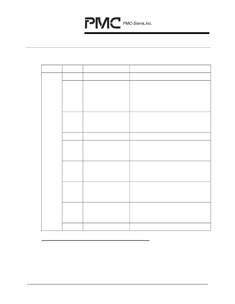
Table 10 RIPP TX Link Configuration Record Structure
WORD
BIT
DATA FIELD
DESCRIPTION
0
31:28
RESERVED
17:16
TX_LINK_GROUP_
TAG
Group tag value of the group which
this TX physical link has been
assigned to.
This field is programmed by PM
during link record initialization.
15:11
TX_LID
LID value for the physical link.
This field is programmed by PM
during link record initialization.
10:5
RESERVED
4
TX_ACTIVE_INT_E
N
TX Active interrupt enable.
‘0’ Interrupt not enabled
‘1’ Interrupt enabled.
FE RX Unusable interrupt enable.
‘0’ Interrupt not enabled
3
FE_RX_UNUSABLE
_INT_EN
‘1’ Interrupt enabled.
FE RX Defect interrupt enable.
‘0’ Interrupt not enabled
2
FE_RX_DEFECT_I
NT_EN
‘1’ Interrupt enabled.
Tx_Timeout interrupt enable.
‘0’ Interrupt not enabled
1
TX_TIMEOUT_INT_
EN
‘1’ Interrupt enabled.
0
RESERVED
RIPP RX Link Configuration Record Memory Area
The RIPP RX Link Configuration Record area is located in the RIPP configuration
memory. There are 8 RIPP RX Link Configuration Records that contain the PM
programmed configuration data for the corresponding RX links. Each record is 1
word deep by 32 bits wide, and is addressed by the physical link number.
相关PDF资料 |
PDF描述 |
|---|---|
| PM7340-PI | SCREW,WING |
| PM7341 | S/UNI INVERSE MULTIPLEXING FOR ATM, 84 LINKS |
| PM7342 | 32 Link Inverse Multiplexer for ATM (IMA) / UNI PHY |
| PM7344 | SATURN QUAD T1/E1 MULTI-PHY USER NETWORK INTERFACE DEVICE |
| PM7345 | SATURN User Network Interface for PDH Applications |
相关代理商/技术参数 |
参数描述 |
|---|---|
| PM7340PI | 制造商:PMC-Sierra 功能描述: |
| PM7340-PI | 制造商:PMC-Sierra 功能描述: |
| PM7342 | 制造商:PMC 制造商全称:PMC 功能描述:32 Link Inverse Multiplexer for ATM (IMA) / UNI PHY |
发布紧急采购,3分钟左右您将得到回复。