- 您现在的位置:买卖IC网 > PDF目录98083 > SME5224AUPA-360 64-BIT, 360 MHz, RISC PROCESSOR PDF资料下载
参数资料
| 型号: | SME5224AUPA-360 |
| 元件分类: | 微控制器/微处理器 |
| 英文描述: | 64-BIT, 360 MHz, RISC PROCESSOR |
| 文件页数: | 6/28页 |
| 文件大小: | 373K |
| 代理商: | SME5224AUPA-360 |
第1页第2页第3页第4页第5页当前第6页第7页第8页第9页第10页第11页第12页第13页第14页第15页第16页第17页第18页第19页第20页第21页第22页第23页第24页第25页第26页第27页第28页
14
SME5224AUPA-360
360 MHz CPU, 4.0 MB E-Cache
UltraSPARC-II CPU Module
July 1999
Sun Microsystems, Inc
UPAACELECTRICAL SPECIFICATIONS
The UPA AC Timing Specications are referenced to the UPA connector. The timing assumes that the clocks
are correctly distributed, (see the section "System Clock Distribution," on page 9). The effective PCB clock
trace lengths (CPU_CLK, UPA_CLK0 and UPA_CLK1) are used to calculate a balanced clock system.
UPA_CLK Module Clocks
All the UPA_CLKx trace pairs are the same length coming from the clock buffer and going to each load. To
calculate UPA_CLK0 and UPA_CLK1 for the module, assume the trace lengths on the module are 9 inches
(which includes the module connector).
CPU_CLK Module Clock
The CPU_CLK trace on the system board is typically only a few inches long. It is the length of the traces used
for the UPA_CLKs from the clock buffer plus the length of UPA_CLK from the clock divider to the clock
buffer minus the effective trace length of CPU_CLK on the module, 18 inches, including the module
connector.
Clock Buffers
The Clock buffer on the systemboard and the clock buffer on the module are assumed to have similar delays.
The clock buffers have a 600 ps delay.
Timing References
The setup, hold and clock to output timing specications are referenced at the module connector for the sig-
nal and at the system UPA device pin. There is no reference point associated with the module since the
module trace lengths provided above are effective lengths only and may not represent actual traces.
The following table species the AC timing parameters for the UPA bus. For waveform illustrations see the
illustration, "Timing Measurement Waveforms," on page 15.
Static signals consist of: UPA_PORT_ID[1:0]; UPA_RATIO; and UPA_SPEED[2:0].
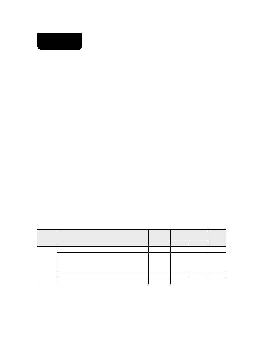
Setup and Hold Time Specications
Symbol
Setup Signals and Hold Time Signals
Waveforms
360 MHz CPU
90 MHz UPA
Unit
Minimum
Maximum
t
SU
Setup time
UPA_DATA [127:0]
1
3.4
–
ns
UPA_ADDR [35:0]
UPA_ADDR_VALID, UPA_REQ_IN [2:0],
UPA_SC_REQ_IN, UPA_DATA_STALL,
UPA_ECC_VALID, UPA_RESET_L, UPA_XIR_L
1
2.9
–
ns
UPA_ECC [15:0]
1
3.4
–
ns
UPA_S_REPLY [3:0]
1
3.4
–
ns
相关PDF资料 |
PDF描述 |
|---|---|
| SME5410MCZ-270 | 64-BIT, 270 MHz, RISC PROCESSOR, XMA |
| SME5434PCI-440 | 64-BIT, 440 MHz, RISC PROCESSOR, XMA |
| SME5434PCI-480 | 64-BIT, 480 MHz, RISC PROCESSOR, XMA |
| SMFR-29C516ESC | 16-BIT ERROR DETECT AND CORRECT CKT, QFP100 |
| SMJ320C26FJ | 16-BIT, 40 MHz, OTHER DSP, CQCC68 |
相关代理商/技术参数 |
参数描述 |
|---|---|
| S-ME6 | 制造商:Phoenix Contact 功能描述:Lock, switching, ME terminal |
| SME6.3T471M8X16LL | 制造商:Texas Instruments 功能描述:EA471-6R3M85 |
| SME6.3VB101M6X11LL | 制造商:未知厂家 制造商全称:未知厂家 功能描述:MINIATURE, GENERAL PURPOSE, SOLVENT PROOF |
| SME6.3VB102M10X12LL | 制造商:United Chemi-Con Inc 功能描述:Capacitor, Aluminium, 1mf, 6.3V, 20±% |
| SME6.3VB103M16X31LL | 功能描述:铝质电解电容器 - 带引线 10KuF 6.3V RoHS:否 制造商:Kemet 引线类型: 电容:220 uF 容差:20 % 电压额定值:25 V 工作温度范围: 端接类型:Radial 外壳直径:8 mm 外壳长度:11 mm 引线间隔:5 mm 产品:General Purpose Electrolytic Capacitors 封装:Bulk |
发布紧急采购,3分钟左右您将得到回复。