- 您现在的位置:买卖IC网 > PDF目录98142 > SST89V516RD-33-C-PI (SILICON STORAGE TECHNOLOGY INC) 8-BIT, FLASH, 33 MHz, MICROCONTROLLER, PDIP40 PDF资料下载
参数资料
| 型号: | SST89V516RD-33-C-PI |
| 厂商: | SILICON STORAGE TECHNOLOGY INC |
| 元件分类: | 微控制器/微处理器 |
| 英文描述: | 8-BIT, FLASH, 33 MHz, MICROCONTROLLER, PDIP40 |
| 封装: | PLASTIC, MS-011AC, DIP-40 |
| 文件页数: | 54/80页 |
| 文件大小: | 934K |
| 代理商: | SST89V516RD-33-C-PI |
第1页第2页第3页第4页第5页第6页第7页第8页第9页第10页第11页第12页第13页第14页第15页第16页第17页第18页第19页第20页第21页第22页第23页第24页第25页第26页第27页第28页第29页第30页第31页第32页第33页第34页第35页第36页第37页第38页第39页第40页第41页第42页第43页第44页第45页第46页第47页第48页第49页第50页第51页第52页第53页当前第54页第55页第56页第57页第58页第59页第60页第61页第62页第63页第64页第65页第66页第67页第68页第69页第70页第71页第72页第73页第74页第75页第76页第77页第78页第79页第80页
58
Data Sheet
FlashFlex51 MCU
SST89E516RD2 / SST89E516RD
SST89V516RD2 / SST89V516RD
2005 Silicon Storage Technology, Inc.
S71273-01-000
3/05
10.0 RESET
A system reset initializes the MCU and begins program
execution at program memory location 0000H. The reset
input for the device is the RST pin. In order to reset the
device, a logic level high must be applied to the RST pin for
at least two machine cycles (24 clocks), after the oscillator
becomes stable. ALE, PSEN# are weakly pulled high dur-
ing reset. During reset, ALE and PSEN# output a high level
in order to perform a proper reset. This level must not be
affected by external element. A system reset will not affect
the 1 KByte of on-chip RAM while the device is running,
however, the contents of the on-chip RAM during power up
are indeterminate. Following reset, all Special Function
Registers (SFR) return to their reset values outlined in
10.1 Power-on Reset
At initial power up, the port pins will be in a random state
until the oscillator has started and the internal reset algo-
rithm has weakly pulled all pins high. Powering up the
device without a valid reset could cause the MCU to
start executing instructions from an indeterminate
location. Such undefined states may inadvertently cor-
rupt the code in the flash.
When power is applied to the device, the RST pin must be
held high long enough for the oscillator to start up (usually
several milliseconds for a low frequency crystal), in addition
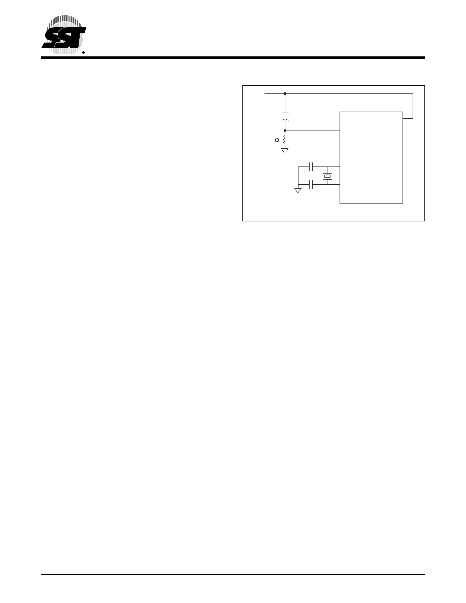
to two machine cycles for a valid power-on reset. An exam-
ple of a method to extend the RST signal is to implement a
RC circuit by connecting the RST pin to VDD through a 10
F capacitor and to VSS through an 8.2K resistor as
shown in Figure 10-1. Note that if an RC circuit is being
used, provisions should be made to ensure the VDD rise
time does not exceed 1 millisecond and the oscillator start-
up time does not exceed 10 milliseconds.
For a low frequency oscillator with slow start-up time the
reset signal must be extended in order to account for the
slow start-up time. This method maintains the necessary
relationship between VDD and RST to avoid programming
at an indeterminate location, which may cause corruption
in the code of the flash. The power-on detection is
designed to work as power up initially, before the voltage
reaches the brown-out detection level. The POF flag in the
PCON register is set to indicate an initial power up condi-
tion. The POF flag will remain active until cleared by soft-
ware. Please see Section 3.6, “Power Control Register
(PCON)” on page 30 for detailed information.
For more information on system level design techniques,
please review the FlashFlex51 MCU: Oscillator Circuit
Design Considerations application note.
FIGURE
10-1: POWER-ON RESET CIRCUIT
10.2 Software Reset
The software reset is executed by changing SFCF[1]
(SWR) from “0” to “1”. A software reset will reset the pro-
gram counter to address 0000H. All SFR registers will be
set to their reset values, except SFCF[1] (SWR), WDTC[2]
(WDTS), and RAM data will not be altered.
10.3 Brown-out Detection Reset
The device includes a brown-out detection circuit to protect
the system from severed supplied voltage VDD fluctuations.
SST89E516RDx internal brown-out detection threshold is
3.85V, SST89V516RDx brown-out detection threshold is
2.35V. For brown-out voltage parameters, please refer to
When VDD drops below this voltage threshold, the brown-
out detector triggers the circuit to generate a brown-out
interrupt but the CPU still runs until the supplied voltage
returns to the brown-out detection voltage VBOD. The
default operation for a brown-out detection is to cause a
processor reset.
VDD must stay below VBOD at least four oscillator clock peri-
ods before the brown-out detection circuit will respond.
Brown-out interrupt can be enabled by setting the EBO bit
in IEA register (address E8H, bit 3). If EBO bit is set and a
brown-out condition occurs, a brown-out interrupt will be
generated to execute the program at location 004BH. It is
required that the EBO bit be cleared by software after the
brown-out interrupt is serviced. Clearing EBO bit when the
brown-out condition is active will properly reset the device.
If brown-out interrupt is not enabled, a brown-out condition
will reset the program to resume execution at location
0000H.
1273 F27.0
VDD
10F
+
-
8.2K
SST89E/V516RDx
RST
XTAL2
XTAL1
C1
C2
相关PDF资料 |
PDF描述 |
|---|---|
| SST89V516RD-33-I-PIE | 8-BIT, FLASH, 33 MHz, MICROCONTROLLER, PDIP40 |
| SST89E516RD-40-I-PIE | 8-BIT, FLASH, 40 MHz, MICROCONTROLLER, PDIP40 |
| SST89V554A-33-C-TQJ | 8-BIT, FLASH, 33 MHz, MICROCONTROLLER, PQFP44 |
| SST89E554A-40-C-NJ | 8-BIT, FLASH, 40 MHz, MICROCONTROLLER, PQCC44 |
| SST89E554A-40-I-TQJ | 8-BIT, FLASH, 40 MHz, MICROCONTROLLER, PQFP44 |
相关代理商/技术参数 |
参数描述 |
|---|---|
| SST89V516RD-33-C-PIE | 功能描述:8位微控制器 -MCU 8-Bit 64K+8K Flash 33MHz 3/16-Bit Timer RoHS:否 制造商:Silicon Labs 核心:8051 处理器系列:C8051F39x 数据总线宽度:8 bit 最大时钟频率:50 MHz 程序存储器大小:16 KB 数据 RAM 大小:1 KB 片上 ADC:Yes 工作电源电压:1.8 V to 3.6 V 工作温度范围:- 40 C to + 105 C 封装 / 箱体:QFN-20 安装风格:SMD/SMT |
| SST89V516RD-33-C-QIF | 制造商:SST 制造商全称:Silicon Storage Technology, Inc 功能描述:FlashFlex MCU |
| SST89V516RD-33-I-QIF | 制造商:SST 制造商全称:Silicon Storage Technology, Inc 功能描述:FlashFlex MCU |
| SST89V52RD2 | 制造商:SST 制造商全称:Silicon Storage Technology, Inc 功能描述:FlashFlex51 MCU |
| SST89V52RD2/RD | 制造商:SST 制造商全称:Silicon Storage Technology, Inc 功能描述:FlashFlex51 MCU |
发布紧急采购,3分钟左右您将得到回复。