- 您现在的位置:买卖IC网 > PDF目录98144 > ST62P35BQ6/XXX (STMICROELECTRONICS) 8-BIT, MROM, 8 MHz, MICROCONTROLLER, PQFP52 PDF资料下载
参数资料
| 型号: | ST62P35BQ6/XXX |
| 厂商: | STMICROELECTRONICS |
| 元件分类: | 微控制器/微处理器 |
| 英文描述: | 8-BIT, MROM, 8 MHz, MICROCONTROLLER, PQFP52 |
| 封装: | PLASTIC, QFP-52 |
| 文件页数: | 52/82页 |
| 文件大小: | 617K |
| 代理商: | ST62P35BQ6/XXX |
第1页第2页第3页第4页第5页第6页第7页第8页第9页第10页第11页第12页第13页第14页第15页第16页第17页第18页第19页第20页第21页第22页第23页第24页第25页第26页第27页第28页第29页第30页第31页第32页第33页第34页第35页第36页第37页第38页第39页第40页第41页第42页第43页第44页第45页第46页第47页第48页第49页第50页第51页当前第52页第53页第54页第55页第56页第57页第58页第59页第60页第61页第62页第63页第64页第65页第66页第67页第68页第69页第70页第71页第72页第73页第74页第75页第76页第77页第78页第79页第80页第81页第82页
56/82
ST62T35B/E35B
4.5.2 CLOCK GENERATION
The UART contains a built-in divider of the MCU
internal clock for most common Baud Rates as
shown in Table 18 . Other baud rate values can be
calculated from the chosen oscillator frequency di-
vided by the Divisor value shown.
The divided clock provides a frequency that is 8
times the desired baud rate. This allows the Data
reception mechanism to provide a 2 to 1 majority
voting system to determine the logic state of the
asynchronous incoming serial logic bit by taking 3
timed samples within the 8 time states.
The bits not sampled provide a buffer to compen-
sate for frequency offsets between sender and re-
ceiver.
4.5.3 DATA TRANSMISSION
Transmission is fixed to a format of one start bit,
nine data bits and one stop bit. The start and stop
bits are automatically generated by the UART.
The nine databits are under control of the user and
are flexible in use. Bits 0..7 are typically used as
data bits while bit 9 is typically used as parity, but
can also be a 9th data bit or an additional Stop bit.
As parity is not generated by the UART, it should
be calculated by program and inserted in the ap-
propriate position of the data (i.e as bit 7 for 7-bit
data, with Bit 9 set to 1 giving two effective stop
bits or as the independent bit 9).
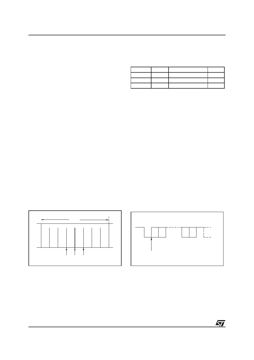
Figure 32. Data Sampling Points
The character options are summarised in the fol-
lowing table.
Table 17. . Character Options
Bit 9 remains in the state programmed for consec-
utive transmissions until changed by the user or
until a character is received when the state of this
bit is changed to that of the incoming bit 9. The
recommended procedure is thus to set the value
of this bit before transmission is started.
Transmission is started by writing to the Data Reg-
ister (the Baud Rate and Bit 9 should be set before
this action). The UARTOE signal switches the out-
put multiplexer to the UART output and a start bit
is sent (a 0 for one bit time) followed by the 8 data
values (lsb first) and the value of the Bit9 bit. The
output is then set to 1 for a period of one bit time to
generate a Stop bit, and then the UARTOE signal
returns the TXD1 line to its alternate I/O function.
The end of transmission is flagged by setting
TXMT to 1 and an interrupt is generated if ena-
bled. The TXMT flag is reset by writing a 0 to the
bit position, it is also cleared automatically when a
new character is written to the Data Register.
TXMT can be set to 1 by software to generate a
software interrupt so care must be taken in manip-
ulating the Control Register.
Figure 33. Character Format
VR02010
1 BIT
0
1
2
345
6
7
8
SAMPLES
Start Bit
8 Data
1 Software Parity
1 Stop
Start Bit
9 Data
No Parity
1 Stop
Start Bit
8 Data
No Parity
2 Stop
Start Bit
7 Data
1 Software Parity
2 Stop
VR02012
POSITION
1
28
10
BIT
START
STOP
BIT
POSSIBLE
NEXT
CHARACTER
START
D0
D1
D7 D8
START OF DATA
9
55
相关PDF资料 |
PDF描述 |
|---|---|
| ST62P35BQ1/XXX | 8-BIT, MROM, 8 MHz, MICROCONTROLLER, PQFP52 |
| ST6235BQ1/XXX | 8-BIT, MROM, 8 MHz, MICROCONTROLLER, PQFP52 |
| ST62P45BQ6/XXX | 8-BIT, MROM, 8 MHz, MICROCONTROLLER, PQFP52 |
| ST62T03CM6E | 8-BIT, OTPROM, 8 MHz, MICROCONTROLLER, PDSO16 |
| ST62T10BM6 | 8-BIT, OTPROM, 8 MHz, MICROCONTROLLER, PDSO20 |
相关代理商/技术参数 |
参数描述 |
|---|---|
| ST62P52C | 制造商:STMicroelectronics 功能描述: |
| ST62P62CM6/MOMTR | 制造商:STMicroelectronics 功能描述: |
| ST62P62CM6/MPITR | 制造商:STMicroelectronics 功能描述: |
| ST62P62CM6/MSATR | 制造商:STMicroelectronics 功能描述: |
| ST62P62CN6/MMMTR | 制造商:STMicroelectronics 功能描述: |
发布紧急采购,3分钟左右您将得到回复。