- 您现在的位置:买卖IC网 > PDF目录69380 > ST92T196A9 (STMICROELECTRONICS) 16-BIT, OTPROM, 24 MHz, MICROCONTROLLER, PDIP56 PDF资料下载
参数资料
| 型号: | ST92T196A9 |
| 厂商: | STMICROELECTRONICS |
| 元件分类: | 微控制器/微处理器 |
| 英文描述: | 16-BIT, OTPROM, 24 MHz, MICROCONTROLLER, PDIP56 |
| 封装: | 0.600 INCH, PLASTIC, SDIP-56 |
| 文件页数: | 51/268页 |
| 文件大小: | 3049K |
| 代理商: | ST92T196A9 |
第1页第2页第3页第4页第5页第6页第7页第8页第9页第10页第11页第12页第13页第14页第15页第16页第17页第18页第19页第20页第21页第22页第23页第24页第25页第26页第27页第28页第29页第30页第31页第32页第33页第34页第35页第36页第37页第38页第39页第40页第41页第42页第43页第44页第45页第46页第47页第48页第49页第50页当前第51页第52页第53页第54页第55页第56页第57页第58页第59页第60页第61页第62页第63页第64页第65页第66页第67页第68页第69页第70页第71页第72页第73页第74页第75页第76页第77页第78页第79页第80页第81页第82页第83页第84页第85页第86页第87页第88页第89页第90页第91页第92页第93页第94页第95页第96页第97页第98页第99页第100页第101页第102页第103页第104页第105页第106页第107页第108页第109页第110页第111页第112页第113页第114页第115页第116页第117页第118页第119页第120页第121页第122页第123页第124页第125页第126页第127页第128页第129页第130页第131页第132页第133页第134页第135页第136页第137页第138页第139页第140页第141页第142页第143页第144页第145页第146页第147页第148页第149页第150页第151页第152页第153页第154页第155页第156页第157页第158页第159页第160页第161页第162页第163页第164页第165页第166页第167页第168页第169页第170页第171页第172页第173页第174页第175页第176页第177页第178页第179页第180页第181页第182页第183页第184页第185页第186页第187页第188页第189页第190页第191页第192页第193页第194页第195页第196页第197页第198页第199页第200页第201页第202页第203页第204页第205页第206页第207页第208页第209页第210页第211页第212页第213页第214页第215页第216页第217页第218页第219页第220页第221页第222页第223页第224页第225页第226页第227页第228页第229页第230页第231页第232页第233页第234页第235页第236页第237页第238页第239页第240页第241页第242页第243页第244页第245页第246页第247页第248页第249页第250页第251页第252页第253页第254页第255页第256页第257页第258页第259页第260页第261页第262页第263页第264页第265页第266页第267页第268页
144/268
- ON SCREEN DISPLAY CONTROLLER (OSD)
OSD CONTROLLER (Cont’d)
Bit 1 = ROU
Rounding control bit
This bit enables or disables the rounding for the
whole row.
0: the rounding is disabled
1: the rounding is enabled
Note: For a 18x26 matrix size, there is no rounding
when the character size is (1X,1Y). For any other
(X,Y) size combinations, the rounding is possible
for the 18x26 font matrix.
Bit 0 = FR
Fringe control bit
This bit enables or disables the fringe for the whole
row. The fringe mechanism can be activated for
any size and matrix format.
0: the character fringe is disabled
1: the character fringe is enabled.
Note: In case of fringe usage in 1Y vertical size
and interlaced mode, a flicker may appear on
screen as the fringe information is built on a field
basis.
8.5.8.4 Active Range
Address in Segment 22h: 2p + 5. See Figure 59.
The active range feature is useful for software con-
trolled smooth vertical scrolling (up or down).
For each row to be displayed, the first line (RS)
and the last line (RE) to be displayed for the cur-
rent row have to be specified.
The two values (RS[3:0] and RE[3:0]) are com-
pared to the row line counter value. If the value of
the counter is outside the active range (less than
RS[3:0] or greater than or equal to RE[3:0]), the
border color is displayed as defined by its at-
tributes. Otherwise, if the counter value is inside
the active range, the normal character pixel
processing and display is done (See Figure 66).
Let’s assume that the start address of the current
row buffer is 2p (even address).
Bits 7:4 = RS[3:0]
Active Range Start value
The RS[3:0] value range is 0h-Ch (0-12) in all cas-
es (9x13 or 18x26 character matrix).
Bits 3:0 = RE[3:0]
Active Range End value
The RE[3:0] value range is 1h-Dh (1-13) in all cas-
es (9x13 or 18x26 character matrix).
Note: For 18x26 matrix characters, the active
range is calculated by pair of TV lines, i.e. the ac-
tive range always starts on the first field and finish-
es on the second field (in interlaced mode).
In case of non-interlaced display mode, the active
range is calculated by pair of TV lines.
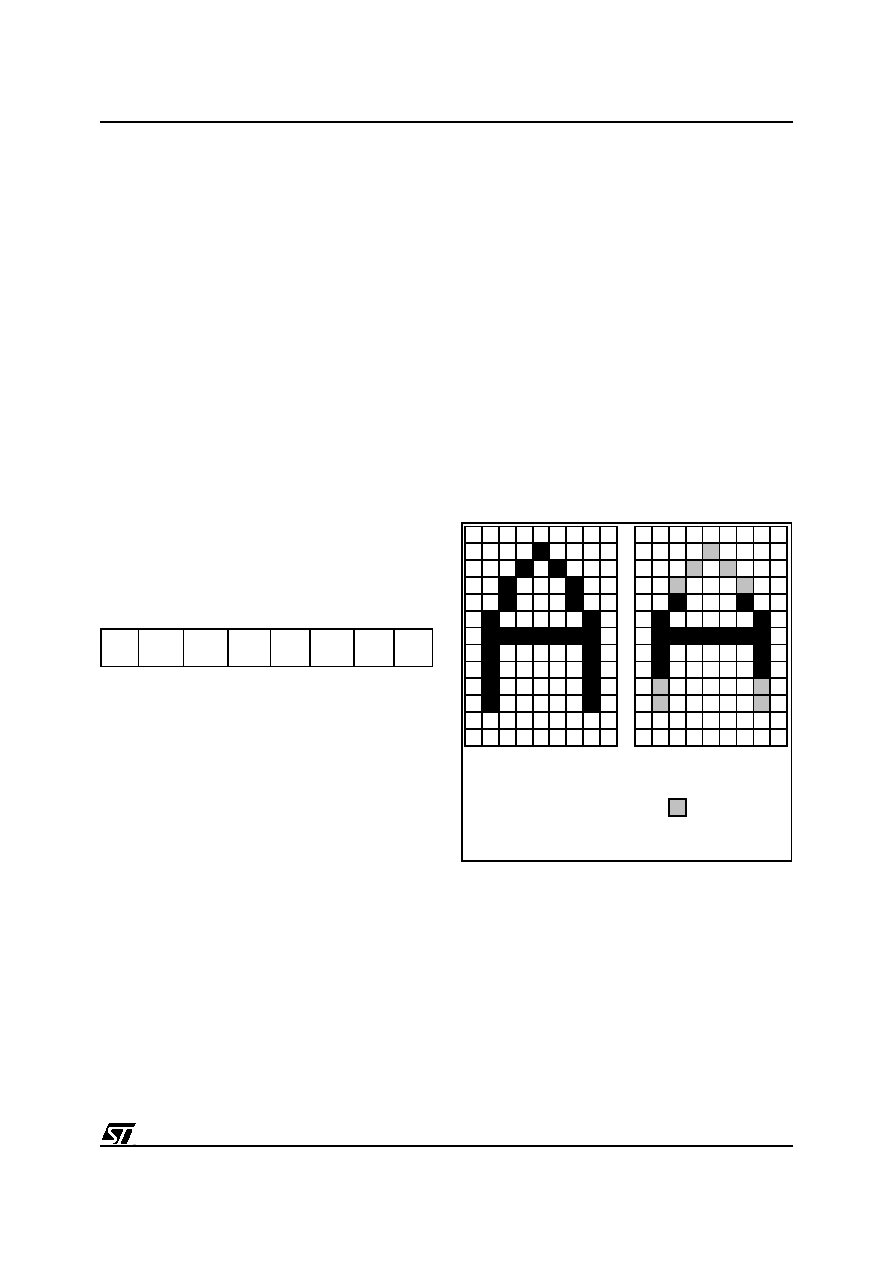
Figure 66. Active Range Example
70
RS3
RS2
RS1
RS0
RE3
RE2
RE1
RE0
0
1
2
3
4
5
6
7
8
9
10
11
12
RS = 0 ; RE = 13
RS = 4 ; RE = 9
ACTIVE RANGE EXAMPLE
Pixel not
displayed
相关PDF资料 |
PDF描述 |
|---|---|
| ST92E196A9 | 16-BIT, EEPROM, 24 MHz, MICROCONTROLLER, CDIP56 |
| ST92T196B7 | 16-BIT, OTPROM, 24 MHz, MICROCONTROLLER, PDIP56 |
| STA2051TR | 32-BIT, FLASH, 66 MHz, RISC MICROCONTROLLER, PQFP64 |
| STA2051ETR | 32-BIT, FLASH, 66 MHz, RISC MICROCONTROLLER, PQFP64 |
| STA2051 | 32-BIT, FLASH, 66 MHz, RISC MICROCONTROLLER, PQFP64 |
相关代理商/技术参数 |
参数描述 |
|---|---|
| ST92T96N9B1/AIN | 制造商:STMicroelectronics 功能描述: |
| ST-930 | 制造商:UNBRANDED 功能描述:MULTIMETER DIGITAL BARGRAPH |
| ST93003 | 功能描述:两极晶体管 - BJT Hi Vltg FAST SWITCH PNP Pwr TRANSISTOR RoHS:否 制造商:STMicroelectronics 配置: 晶体管极性:PNP 集电极—基极电压 VCBO: 集电极—发射极最大电压 VCEO:- 40 V 发射极 - 基极电压 VEBO:- 6 V 集电极—射极饱和电压: 最大直流电集电极电流: 增益带宽产品fT: 直流集电极/Base Gain hfe Min:100 A 最大工作温度: 安装风格:SMD/SMT 封装 / 箱体:PowerFLAT 2 x 2 |
| ST9300403SS | 制造商:Seagate Technology 功能描述:- Bulk |
| ST9300453SS | 制造商:Seagate Technology 功能描述:- Bulk |
发布紧急采购,3分钟左右您将得到回复。