- 您现在的位置:买卖IC网 > PDF目录98215 > TFP501PZP (TEXAS INSTRUMENTS INC) SPECIALTY CONSUMER CIRCUIT, PQFP100 PDF资料下载
参数资料
| 型号: | TFP501PZP |
| 厂商: | TEXAS INSTRUMENTS INC |
| 元件分类: | 消费家电 |
| 英文描述: | SPECIALTY CONSUMER CIRCUIT, PQFP100 |
| 封装: | 14 X 14 MM, 1 MM HEIGHT, 0.50 MM PITCH, GREEN, PLASTIC, HTQFP-100 |
| 文件页数: | 20/24页 |
| 文件大小: | 373K |
| 代理商: | TFP501PZP |
TFP501
PanelBus HDCP DIGITAL RECEIVER
SLDS127B JULY 2001 REVISED AUGUST 2002
5
POST OFFICE BOX 655303
DALLAS, TEXAS 75265
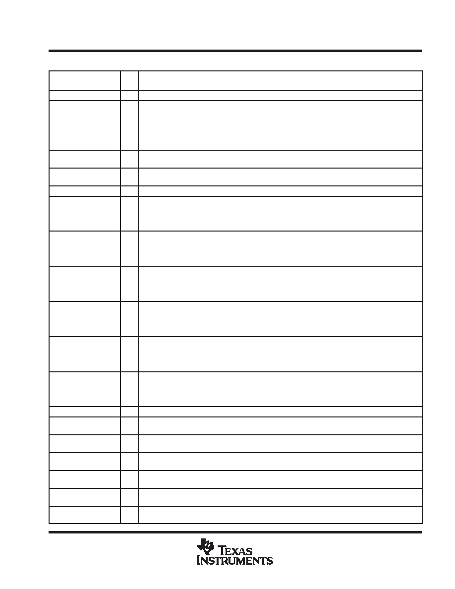
Terminal Functions (Continued)
TERMINAL
I/O
DESCRIPTION
NAME
NO.
I/O
DESCRIPTION
PGND
98
PLL ground – Ground reference and current return for internal PLL.
PIXS
4
I
Pixel select—Selects between one or two pixel per clock output modes. During 2-pixel/clock mode, both even
pixels, QE[23:0], and odd pixels, QO[23:0], are output in tandem on a given clock cycle. During 1 pixel/clock,
even and odd pixels are output sequentially, one at a time, with the even pixel first, on the even pixel bus,
QE[23:0]. (The first pixel per line is pixel-0, the even pixel. The second pixel per line is pixel-1, the odd pixel.)
High: 2 pixel/clock
Low: 1 pixel/clock
PROM_SCL
95
I/O
EEPROM_serial clock—I2C clock for EEPROM interface data. External pullup resistors = 10 k
and 3.3 V
tolerant.
PROM_SDA
96
I/O
EEPROM_serial data—I2C data for EEPROM interface data. External pullup resistors = 10 k
and 3.3 V
tolerant.
PVDD (1, 2)
97, 99
PLL VDD—Power supply for internal PLL. Nominally 3.3 V.
QE[0:7]
1017
O
Even blue pixel output—Output for even and odd blue pixels when in 1-pixel/clock mode. Output for even only
blue pixel when in 2-pixel/clock mode. Output data is synchronized to the output data clock, ODCK.
LSB: QE0/pin 10
MSB: QE7/pin 17
QE[8:15]
2027
O
Even green pixel output—Output for even and odd green pixels when in 1-pixel/clock mode. Output for even
only green pixel when in 2-pixel/clock mode. Output data is synchronized to the output data clock, ODCK.
LSB: QE8/pin 20
MSB: QE15/pin 27
QE[16:23]
3037
O
Even red pixel output—Output for even and odd red pixels when in 1-pixel/clock mode. Output for even only
red pixel when in 2-pixel/clock mode. Output data is synchronized to the output data clock, ODCK.
LSB: QE16/pin 30
MSB: QE23/pin 37
QO[0:7]
4956
O
Odd blue pixel output—Output for odd only blue pixel when in 2-pixel/clock mode. Not used, and held low,
when in 1-pixel/clock mode. Output data is synchronized to the output data clock, ODCK.
LSB: QO0/pin 49
MSB: QO7/pin 56
QO[8:15]
5966
O
Odd green pixel output—Output for odd only green pixel when in 2-pixel/clock mode. Not used, and held low,
when in 1-pixel/clock mode. Output data is synchronized to the output data clock, ODCK.
LSB: QO8/pin 59
MSB: QO15/pin 66
QO[16:23]
6975,
77
O
Odd red pixel output—Output for odd only red pixel when in 2-pixel/clock mode. Not used, and held low, when
in 1-pixel/clock mode. Output data is synchronized to the output data clock, ODCK.
LSB: QO16/pin 69
MSB: QO23/pin 77
RSVD
42
O
Reserved—Must be tied high for normal operation.
Rx2+
80
I
Channel-2 positive receiver input—Positive side of channel-2 T.M.D.S. low voltage signal differential input
pair. Channel-2 receives red pixel data in active display and CTL2 control signal during blanking.
Rx2
81
I
Channel-2 negative receiver input—Negative side of channel-2 T.M.D.S. low voltage signal differential input
pair.
Rx1+
83
I
Channel-1 positive receiver input—Positive side of channel-1 T.M.D.S. low voltage signal differential input
pair. Channel1 receives green pixel data in active display and CTL1 control signal during blanking.
Rx1
84
I
Channel-1 negative receiver input—Negative side of channel-1 T.M.D.S. low voltage signal differential input
pair.
Rx0+
86
I
Channel-0 positive receiver input—Positive side of channel-0 T.M.D.S. low voltage signal differential input
pair. Channel-0 receives blue pixel data in active display and HSYNC, VSYNC control signals during blanking.
Rx0
87
I
Channel-0 negative receiver input—Negative side of channel-0 T.M.D.S. low voltage signal differential input
pair.
相关PDF资料 |
PDF描述 |
|---|---|
| TFP503PZPG4 | SPECIALTY CONSUMER CIRCUIT, PQFP100 |
| TFP503PZP | SPECIALTY CONSUMER CIRCUIT, PQFP100 |
| TFP510PAPG4 | SPECIALTY CONSUMER CIRCUIT, PQFP64 |
| TFP510PAP | SPECIALTY CONSUMER CIRCUIT, PQFP64 |
| TFP513PAPG4 | SPECIALTY CONSUMER CIRCUIT, PQFP64 |
相关代理商/技术参数 |
参数描述 |
|---|---|
| TFP501PZPG4 | 制造商:Texas Instruments 功能描述:PNL BUS HDCP DGTL RCVR 100HTQFP - Rail/Tube |
| TFP503 | 制造商:TI 制造商全称:Texas Instruments 功能描述:PANELBUS HDCP DIGITAL RECEIVER |
| TFP503PZP | 制造商:Texas Instruments 功能描述:PANELBUS DVI RECEIVER 165MHZ PLUS HDCP |
| TFP503PZPG4 | 制造商:Texas Instruments 功能描述:DGTL RCVR 1RX 100HTQFP - Rail/Tube |
| TFP50N06 | 制造商:TAK_CHEONG 制造商全称:Tak Cheong Electronics (Holdings) Co.,Ltd 功能描述:N-Channel Power MOSFET 50A, 60V, 0.023Ω |
发布紧急采购,3分钟左右您将得到回复。