- 您现在的位置:买卖IC网 > PDF目录98280 > TPS2540RTET (TEXAS INSTRUMENTS INC) 1-CHANNEL POWER SUPPLY SUPPORT CKT, PQCC16 PDF资料下载
参数资料
| 型号: | TPS2540RTET |
| 厂商: | TEXAS INSTRUMENTS INC |
| 元件分类: | 电源管理 |
| 英文描述: | 1-CHANNEL POWER SUPPLY SUPPORT CKT, PQCC16 |
| 封装: | GREEN, PLASTIC, WQFN-16 |
| 文件页数: | 12/37页 |
| 文件大小: | 999K |
| 代理商: | TPS2540RTET |
第1页第2页第3页第4页第5页第6页第7页第8页第9页第10页第11页当前第12页第13页第14页第15页第16页第17页第18页第19页第20页第21页第22页第23页第24页第25页第26页第27页第28页第29页第30页第31页第32页第33页第34页第35页第36页第37页
SLVSAG2A
– OCTOBER 2010 – REVISED APRIL 2011
This integrated circuit can be damaged by ESD. Texas Instruments recommends that all integrated circuits be handled with
appropriate precautions. Failure to observe proper handling and installation procedures can cause damage.
ESD damage can range from subtle performance degradation to complete device failure. Precision integrated circuits may be more
susceptible to damage because very small parametric changes could cause the device not to meet its published specifications.
DESCRIPTION (CONT.)
The TPS2540A auto detect mode also has a longer detach detection time, so that it can support certain unique
non-compliant devices. The TPS2540/40A/41 power-distribution switch is intended for applications where heavy
capacitive loads and short-circuits are likely to be encountered, incorporating a 73-m
Ω, N-channel MOSFET in a
single package. Constant-current mode is used when the output load exceeds the current-limit threshold.
ILIM_SEL logic input selects one of two current-limit thresholds, each one being individually adjustable via an
external resistor. Additional USB switch features include a de-glitched output fault reporting (FAULT), and a
logic-level enable EN (TPS2540/40A) or OUT discharge control DSC (TPS2541). With the TPS2540/40A, the
mode
“000” is used to force an output discharge.
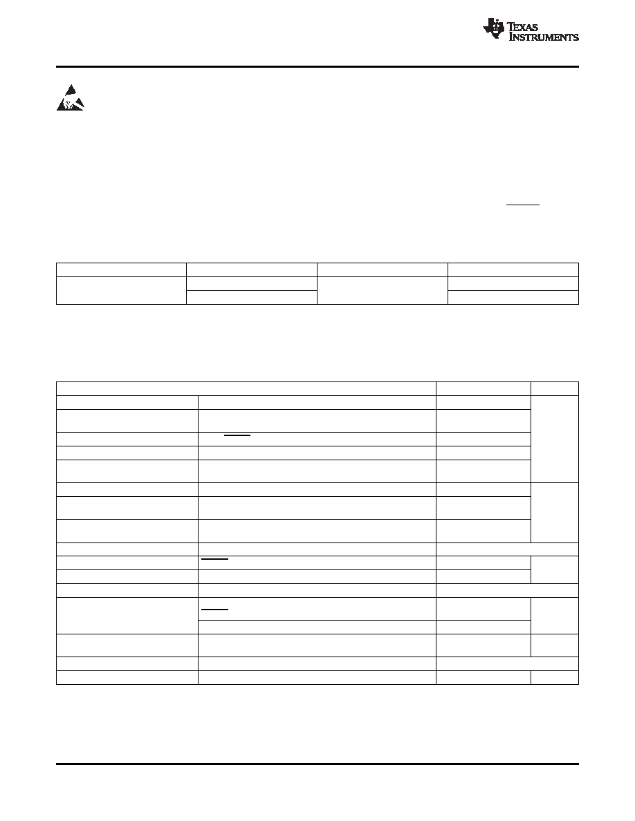
PRODUCT INFORMATION(1)
TA
FUNCTION
PACKAGE
MARKING
Enable
2540
-40
°C to 85°C
QFN16
Output Discharge
2541
(1)
For the most current package and ordering information, see the Package Option Addendum at the end of this document, or visit the
device product folder on www.ti.com.
ABSOLUTE MAXIMUM RATINGS
(1)
over operating free-air temperature range, voltages are referenced to GND (unless otherwise noted)
PARAMETER
MIN
MAX
UNIT
Supply voltage range
IN
-0.3
7
Input voltage range
EN (TPS2540/40A), DSC (TPS2541), ILIM0, ILIM1, ILIM_SEL,
-0.3
7
CTL1, CTL2, CTL3
Voltage range
OUT, FAULT (2)
-0.3
7
V
Voltage range
IN to OUT
-7
7
Voltage range
DP_IN, DM_IN, DP_OUT, DM_OUT
(IN + 0.3)
-0.3
or 5.7
Input clamp current
DP_IN, DM_IN, DP_OUT, DM_OUT
±20
Continuous current in SDP or CDP
DP_IN to DP_OUT or DM_IN to DM_OUT
±100
mode
mA
Continuous current in BC1.2 DCP
DP_IN to DM_IN
±35
mode
Continuous output current
IOUT
Internally limited
Continuous output sink current
FAULT
25
mA
Continuous output source current
ILIM0, ILIM1
1
Continuous total power dissipation
Internally limited
ESD rating, Human Body Model
IN, ILIM_SEL, EN, DSC, CTL1, CTL2, CTL3, N/C, OUT,
2
(HBM)
FAULT, GND, ILIM1, ILIM0
kV
DP_IN, DM_IN, DP_OUT, DM_OUT
8
ESD rating, Charged Device Model
500
V
(CDM)
Operating Junction temperature
TJ
Internally limited
Storage temperature range
Tstg
-65
150
°C
(1)
Stresses beyond those listed under
"absolute maximum ratings" may cause permanent damage to the device. These are stress ratings
only and functional operation of the device at these or any other conditions beyond those indicated under
"recommended operating
conditions
" is not implied. Exposure to absolute-maximum-rated conditions for extended periods may affect device reliability.
(2)
Do not apply external voltage sources directly.
2
Copyright
2010–2011, Texas Instruments Incorporated
相关PDF资料 |
PDF描述 |
|---|---|
| TPS2541RTET | 1-CHANNEL POWER SUPPLY SUPPORT CKT, PQCC16 |
| TPS2550DBV | 1-CHANNEL POWER SUPPLY SUPPORT CKT, PDSO6 |
| TPS2551DRVR | 1-CHANNEL POWER SUPPLY SUPPORT CKT, PDSO6 |
| TPS2551DRVTG4 | 1-CHANNEL POWER SUPPLY SUPPORT CKT, PDSO6 |
| TPS2551DRVRG4 | 1-CHANNEL POWER SUPPLY SUPPORT CKT, PDSO6 |
相关代理商/技术参数 |
参数描述 |
|---|---|
| TPS2540RTET | 制造商:Texas Instruments 功能描述:IC USB SWITCH 2.6GHZ 16-WQFN |
| TPS2541ARTER | 功能描述:电源开关 IC - USB USB Charging Port Pwr Sw & Controller RoHS:否 制造商:Micrel 电源电压-最小:2.7 V 电源电压-最大:5.5 V 最大工作温度:+ 85 C 最小工作温度:- 40 C 封装 / 箱体:SOIC-8 封装:Tube |
| TPS2541ARTET | 功能描述:电源开关 IC - USB USB Charging Port Pwr Sw & Controller RoHS:否 制造商:Micrel 电源电压-最小:2.7 V 电源电压-最大:5.5 V 最大工作温度:+ 85 C 最小工作温度:- 40 C 封装 / 箱体:SOIC-8 封装:Tube |
| TPS2541RTER | 功能描述:电源开关 IC - USB USB Charging Port Pwr Swtch &Contrller RoHS:否 制造商:Micrel 电源电压-最小:2.7 V 电源电压-最大:5.5 V 最大工作温度:+ 85 C 最小工作温度:- 40 C 封装 / 箱体:SOIC-8 封装:Tube |
| TPS2541RTET | 功能描述:电源开关 IC - USB USB Charging Port Pwr Swtch &Contrller RoHS:否 制造商:Micrel 电源电压-最小:2.7 V 电源电压-最大:5.5 V 最大工作温度:+ 85 C 最小工作温度:- 40 C 封装 / 箱体:SOIC-8 封装:Tube |
发布紧急采购,3分钟左右您将得到回复。