- 您现在的位置:买卖IC网 > PDF目录98280 > TPS2540RTET (TEXAS INSTRUMENTS INC) 1-CHANNEL POWER SUPPLY SUPPORT CKT, PQCC16 PDF资料下载
参数资料
| 型号: | TPS2540RTET |
| 厂商: | TEXAS INSTRUMENTS INC |
| 元件分类: | 电源管理 |
| 英文描述: | 1-CHANNEL POWER SUPPLY SUPPORT CKT, PQCC16 |
| 封装: | GREEN, PLASTIC, WQFN-16 |
| 文件页数: | 18/37页 |
| 文件大小: | 999K |
| 代理商: | TPS2540RTET |
第1页第2页第3页第4页第5页第6页第7页第8页第9页第10页第11页第12页第13页第14页第15页第16页第17页当前第18页第19页第20页第21页第22页第23页第24页第25页第26页第27页第28页第29页第30页第31页第32页第33页第34页第35页第36页第37页
SLVSAG2A
– OCTOBER 2010 – REVISED APRIL 2011
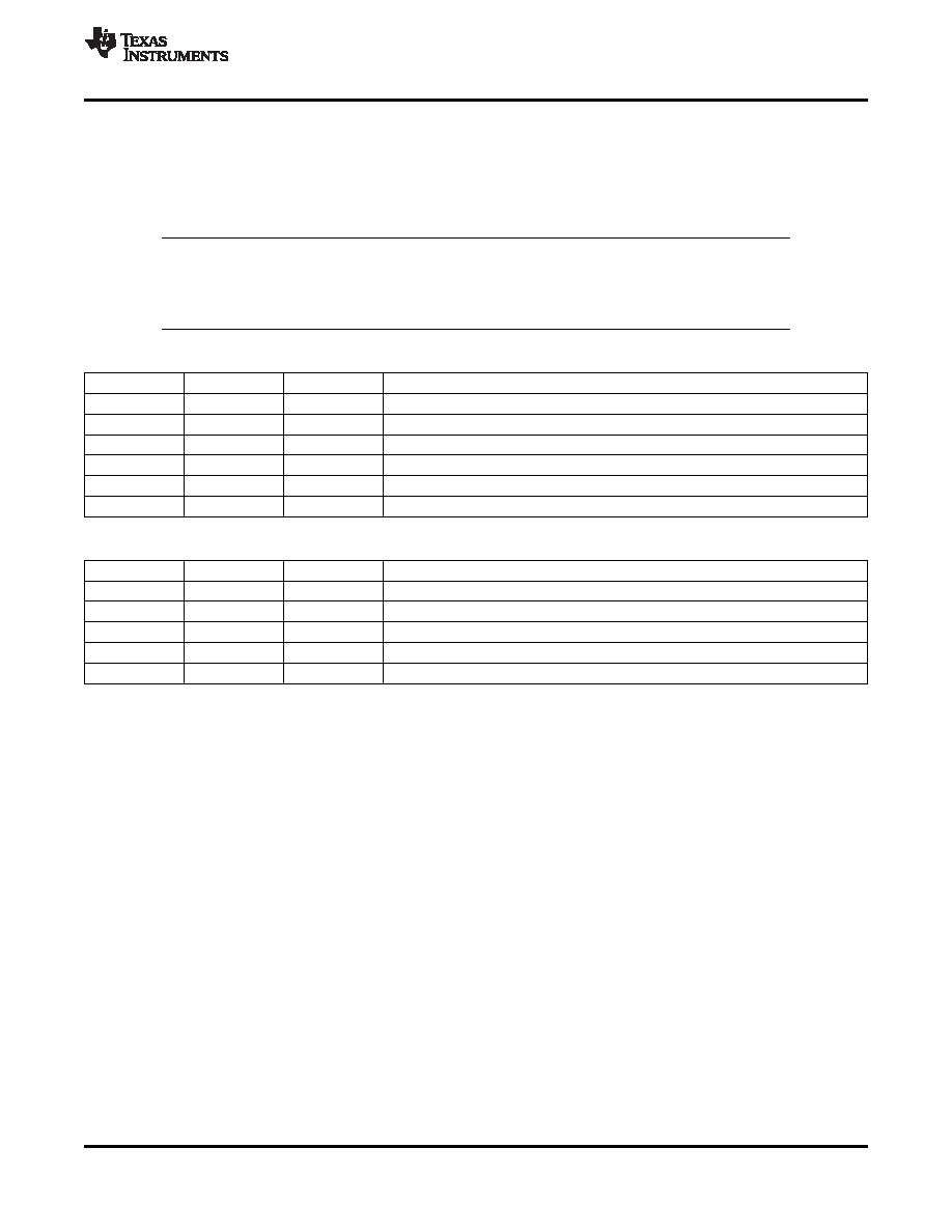
Logic Control Modes
Both the TPS2540/40A and TPS2541 support the listed standards above for the SDP, CDP and DCP modes
using the CTL1, CTL2, and CTL3 logic I/O control pins, although their truth tables are different as shown below.
The different CTLx settings correspond to the different types of charge modes. Also, using the Auto-Detect
Mode, the Divider Mode or BC1.2 / YD/T 1591-2009 can be automatically selected without external user
interaction.
NOTE
With the TPS254040A, if the
“000” mode is selected, the power switch will be turned off
and an output discharge resistor will be connected, while the data line switches will be
turned off.
Table 2. TPS2540/40A Control Truth Table
CTL1
CTL2
CTL3
MODE
0
OUT discharge, power switch OFF.
0
X
1
Dedicated charging port, auto-detect.
X
1
0
Standard downstream port, USB 2.0 Mode.
1
0
Dedicated charging port, BC1.2 only.
1
0
1
Dedicated charging port, Divider Mode only.
1
Charging downstream port, BC1.2.
Table 3. TPS2541 Control Truth Table
CTL1
CTL2
CTL3
MODE
0
X
Dedicated charging port, auto-detect.
0
1
X
Dedicated charging port, BC1.2.
1
0
X
Dedicated charging port, Divider Mode only.
1
0
Standard downstream port, USB 2.0 Mode.
1
Charging downstream port, BC1.2.
Output Discharge
To allow a charging port to renegotiate current with a portable device, TPS2540/40A/41 uses the VBUS
discharge function. It proceeds by turning off the power switch while discharging OUT, then turning back ON the
power switch to reassert the OUT voltage.
This discharge function is automatically applied when a change at the CTLx lines results in any of the following
mode transitions.
Any transition to and from CDP
Any transition to and from SDP
In addition to this, a direct discharge control, DSC, is available with the TPS2541, while with the TPS2540/40A, a
discharge can be achieved using the mode
“000”.
Overcurrent Protection
When an over-current condition is detected, the device maintains a constant output current and reduces the
output voltage accordingly. Two possible overload conditions can occur. In the first condition, the output has
been shorted before the device is enabled or before VIN has been applied.
The TPS2540/40A/41 senses the short and immediately switches into a constant-current output. In the second
condition, a short or an overload occurs while the device is enabled. At the instant the overload occurs, high
currents may flow for nominally one to two microseconds before the current-limit circuit can react. The device
operates in constant-current mode after the current-limit circuit has responded. Complete shutdown occurs only if
the fault is present long enough to activate thermal limiting. The device will remain off until the junction
temperature cools approximately 10
°C and will then re-start. The device will continue to cycle on/off until the
over-current condition is removed.
Copyright
2010–2011, Texas Instruments Incorporated
25
相关PDF资料 |
PDF描述 |
|---|---|
| TPS2541RTET | 1-CHANNEL POWER SUPPLY SUPPORT CKT, PQCC16 |
| TPS2550DBV | 1-CHANNEL POWER SUPPLY SUPPORT CKT, PDSO6 |
| TPS2551DRVR | 1-CHANNEL POWER SUPPLY SUPPORT CKT, PDSO6 |
| TPS2551DRVTG4 | 1-CHANNEL POWER SUPPLY SUPPORT CKT, PDSO6 |
| TPS2551DRVRG4 | 1-CHANNEL POWER SUPPLY SUPPORT CKT, PDSO6 |
相关代理商/技术参数 |
参数描述 |
|---|---|
| TPS2540RTET | 制造商:Texas Instruments 功能描述:IC USB SWITCH 2.6GHZ 16-WQFN |
| TPS2541ARTER | 功能描述:电源开关 IC - USB USB Charging Port Pwr Sw & Controller RoHS:否 制造商:Micrel 电源电压-最小:2.7 V 电源电压-最大:5.5 V 最大工作温度:+ 85 C 最小工作温度:- 40 C 封装 / 箱体:SOIC-8 封装:Tube |
| TPS2541ARTET | 功能描述:电源开关 IC - USB USB Charging Port Pwr Sw & Controller RoHS:否 制造商:Micrel 电源电压-最小:2.7 V 电源电压-最大:5.5 V 最大工作温度:+ 85 C 最小工作温度:- 40 C 封装 / 箱体:SOIC-8 封装:Tube |
| TPS2541RTER | 功能描述:电源开关 IC - USB USB Charging Port Pwr Swtch &Contrller RoHS:否 制造商:Micrel 电源电压-最小:2.7 V 电源电压-最大:5.5 V 最大工作温度:+ 85 C 最小工作温度:- 40 C 封装 / 箱体:SOIC-8 封装:Tube |
| TPS2541RTET | 功能描述:电源开关 IC - USB USB Charging Port Pwr Swtch &Contrller RoHS:否 制造商:Micrel 电源电压-最小:2.7 V 电源电压-最大:5.5 V 最大工作温度:+ 85 C 最小工作温度:- 40 C 封装 / 箱体:SOIC-8 封装:Tube |
发布紧急采购,3分钟左右您将得到回复。