- 您现在的位置:买卖IC网 > PDF目录205935 > XC5204-6TQ144C (XILINX INC) Field Programmable Gate Arrays PDF资料下载
参数资料
| 型号: | XC5204-6TQ144C |
| 厂商: | XILINX INC |
| 元件分类: | FPGA |
| 英文描述: | Field Programmable Gate Arrays |
| 中文描述: | FPGA, 120 CLBS, 4000 GATES, 83 MHz, PQFP144 |
| 封装: | PLASTIC, TQFP-144 |
| 文件页数: | 14/73页 |
| 文件大小: | 598K |
| 代理商: | XC5204-6TQ144C |
第1页第2页第3页第4页第5页第6页第7页第8页第9页第10页第11页第12页第13页当前第14页第15页第16页第17页第18页第19页第20页第21页第22页第23页第24页第25页第26页第27页第28页第29页第30页第31页第32页第33页第34页第35页第36页第37页第38页第39页第40页第41页第42页第43页第44页第45页第46页第47页第48页第49页第50页第51页第52页第53页第54页第55页第56页第57页第58页第59页第60页第61页第62页第63页第64页第65页第66页第67页第68页第69页第70页第71页第72页第73页
R
November 5, 1998 (Version 5.2)
7-103
XC5200 Series Field Programmable Gate Arrays
7
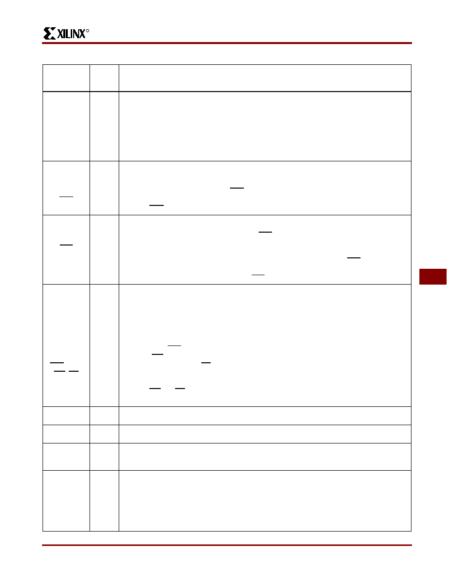
TDI, TCK,
TMS
I
I/O
or I
(JTAG)
If boundary scan is used, these pins are Test Data In, Test Clock, and Test Mode Select
inputs respectively. They come directly from the pads, bypassing the IOBs. These pins
can also be used as inputs to the CLB logic after configuration is completed.
If the BSCAN symbol is not placed in the design, all boundary scan functions are inhib-
ited once configuration is completed, and these pins become user-programmable I/O.
In this case, they must be called out by special schematic definitions. To use these pins,
place the library components TDI, TCK, and TMS instead of the usual pad symbols. In-
put or output buffers must still be used.
HDC
O
I/O
High During Configuration (HDC) is driven High until the I/O go active. It is available as
a control output indicating that configuration is not yet completed. After configuration,
HDC is a user-programmable I/O pin.
LDC
OI/O
Low During Configuration (LDC) is driven Low until the I/O go active. It is available as a
control output indicating that configuration is not yet completed. After configuration,
LDC is a user-programmable I/O pin.
INIT
I/O
Before and during configuration, INIT is a bidirectional signal. A 1 k
- 10 k external
pull-up resistor is recommended.
As an active-Low open-drain output, INIT is held Low during the power stabilization and
internal clearing of the configuration memory. As an active-Low input, it can be used
to hold the FPGA in the internal WAIT state before the start of configuration. Master
mode devices stay in a WAIT state an additional 50 to 250
s after INIT has gone High.
During configuration, a Low on this output indicates that a configuration data error has
occurred. After the I/O go active, INIT is a user-programmable I/O pin.
GCK1 -
GCK4
Weak
Pull-up
I or I/O
Four Global inputs each drive a dedicated internal global net with short delay and min-
imal skew. These internal global nets can also be driven from internal logic. If not used
to drive a global net, any of these pins is a user-programmable I/O pin.
The GCK1-GCK4 pins provide the shortest path to the four Global Buffers. Any input
pad symbol connected directly to the input of a BUFG symbol is automatically placed on
one of these pins.
CS0, CS1,
WS, RS
II/O
These four inputs are used in Asynchronous Peripheral mode. The chip is selected
when CS0 is Low and CS1 is High. While the chip is selected, a Low on Write Strobe
(WS) loads the data present on the D0 - D7 inputs into the internal data buffer. A Low
on Read Strobe (RS) changes D7 into a status output — High if Ready, Low if Busy —
and drives D0 - D6 High.
In Express mode, CS1 is used as a serial-enable signal for daisy-chaining.
WS and RS should be mutually exclusive, but if both are Low simultaneously, the Write
Strobe overrides. After configuration, these are user-programmable I/O pins.
A0 - A17
O
I/O
During Master Parallel configuration, these 18 output pins address the configuration
EPROM. After configuration, they are user-programmable I/O pins.
D0 - D7
I
I/O
During Master Parallel, Peripheral, and Express configuration, these eight input pins re-
ceive configuration data. After configuration, they are user-programmable I/O pins.
DIN
I
I/O
During Slave Serial or Master Serial configuration, DIN is the serial configuration data
input receiving data on the rising edge of CCLK. During Parallel configuration, DIN is
the D0 input. After configuration, DIN is a user-programmable I/O pin.
DOUT
O
I/O
During configuration in any mode but Express mode, DOUT is the serial configuration
data output that can drive the DIN of daisy-chained slave FPGAs. DOUT data changes
on the falling edge of CCLK.
In Express mode, DOUT is the status output that can drive the CS1 of daisy-chained
FPGAs, to enable and disable downstream devices.
After configuration, DOUT is a user-programmable I/O pin.
Table 9: Pin Descriptions (Continued)
Pin Name
I/O
During
Config.
I/O
After
Config.
Pin Description
相关PDF资料 |
PDF描述 |
|---|---|
| XC5206-3BG225C | Field Programmable Gate Arrays |
| XC5206-3BG352C | Field Programmable Gate Arrays |
| XC5206-3HQ208C | Field Programmable Gate Arrays |
| XC5206-3HQ240C | Field Programmable Gate Arrays |
| XC5206-3PG156C | Field Programmable Gate Arrays |
相关代理商/技术参数 |
参数描述 |
|---|---|
| XC5204-6TQ144I | 制造商:Xilinx 功能描述: |
| XC5204-6TQ176C | 制造商:XILINX 制造商全称:XILINX 功能描述:Field Programmable Gate Arrays |
| XC5204-6VQ100C | 功能描述:IC FPGA 120 CLB'S 100-VQFP RoHS:否 类别:集成电路 (IC) >> 嵌入式 - FPGA(现场可编程门阵列) 系列:XC5200 产品变化通告:XC4000(E,L) Discontinuation 01/April/2002 标准包装:24 系列:XC4000E/X LAB/CLB数:100 逻辑元件/单元数:238 RAM 位总计:3200 输入/输出数:80 门数:3000 电源电压:4.5 V ~ 5.5 V 安装类型:表面贴装 工作温度:-40°C ~ 100°C 封装/外壳:120-BCBGA 供应商设备封装:120-CPGA(34.55x34.55) |
| XC5204-6VQ100I | 制造商:Xilinx 功能描述: |
| XC5204-6VQ64C | 制造商:XILINX 制造商全称:XILINX 功能描述:Field Programmable Gate Arrays |
发布紧急采购,3分钟左右您将得到回复。