- 您现在的位置:买卖IC网 > PDF目录205935 > XC5204-6TQ144C (XILINX INC) Field Programmable Gate Arrays PDF资料下载
参数资料
| 型号: | XC5204-6TQ144C |
| 厂商: | XILINX INC |
| 元件分类: | FPGA |
| 英文描述: | Field Programmable Gate Arrays |
| 中文描述: | FPGA, 120 CLBS, 4000 GATES, 83 MHz, PQFP144 |
| 封装: | PLASTIC, TQFP-144 |
| 文件页数: | 17/73页 |
| 文件大小: | 598K |
| 代理商: | XC5204-6TQ144C |
第1页第2页第3页第4页第5页第6页第7页第8页第9页第10页第11页第12页第13页第14页第15页第16页当前第17页第18页第19页第20页第21页第22页第23页第24页第25页第26页第27页第28页第29页第30页第31页第32页第33页第34页第35页第36页第37页第38页第39页第40页第41页第42页第43页第44页第45页第46页第47页第48页第49页第50页第51页第52页第53页第54页第55页第56页第57页第58页第59页第60页第61页第62页第63页第64页第65页第66页第67页第68页第69页第70页第71页第72页第73页
R
XC5200 Series Field Programmable Gate Arrays
7-106
November 5, 1998 (Version 5.2)
Express Mode
Express mode is similar to Slave Serial mode, except the
data is presented in parallel format, and is clocked into the
target device a byte at a time rather than a bit at a time. The
data is loaded in parallel into eight different columns: it is
not internally serialized. Eight bits of configuration data are
loaded with every CCLK cycle, therefore this configuration
mode runs at eight times the data rate of the other six
modes. In this mode the XC5200 family is capable of sup-
porting a CCLK frequency of 10 MHz, which is equivalent to
an 80 MHz serial rate, because eight bits of configuration
data are being loaded per CCLK cycle. An XC5210 in the
Express mode, for instance, can be configured in about 2
ms. The Express mode does not support CRC error check-
ing, but does support constant-field error checking. A
length count is not used in Express mode.
In the Express configuration mode, an external signal
drives the CCLK input(s). The first byte of parallel configu-
ration data must be available at the D inputs of the FPGA
devices a short set-up time before the second rising CCLK
edge. Subsequent data bytes are clocked in on each con-
secutive rising CCLK edge. See Figure 38 on page 123.
Bitstream generation currently generates a bitstream suffi-
cient to program in all configuration modes except Express.
Extra CCLK cycles are necessary to complete the configu-
ration, since in this mode data is read at a rate of eight bits
per CCLK cycle instead of one bit per cycle. Normally the
entire start-up sequence requires a number of bits that is
equal to the number of CCLK cycles needed. An additional
five CCLKs (equivalent to 40 extra bits) will guarantee com-
pletion of configuration, regardless of the start-up options
chosen.
Multiple slave devices with identical configurations can be
wired with parallel D0-D7 inputs.
In this way, multiple
devices can be configured simultaneously.
Pseudo Daisy Chain
Multiple devices with different configurations can be con-
nected together in a pseudo daisy chain, provided that all of
the devices are in Express mode. A single combined bit-
stream is used to configure the chain of Express mode
devices, but the input data bus must drive D0-D7 of each
device. Tie High the CS1 pin of the first device to be config-
ured, or leave it floating in the XC5200 since it has an inter-
nal pull-up. Connect the DOUT pin of each FPGA to the
CS1 pin of the next device in the chain. The D0-D7 inputs
are wired to each device in parallel. The DONE pins are
wired together, with one or more internal DONE pull-ups
activated. Alternatively, a 4.7 k
external resistor can be
used, if desired. (See Figure 37 on page 122.) CCLK pins
are tied together.
The requirement that all DONE pins in a daisy chain be
wired together applies only to Express mode, and only if all
devices in the chain are to become active simultaneously.
All devices in Express mode are synchronized to the DONE
pin.
User I/O for each device become active after the
DONE pin for that device goes High. (The exact timing is
determined by options to the bitstream generation soft-
ware.) Since the DONE pin is open-drain and does not
drive a High value, tying the DONE pins of all devices
together prevents all devices in the chain from going High
until the last device in the chain has completed its configu-
ration cycle.
The status pin DOUT is pulled LOW two internal-oscillator
cycles (nominally 1 MHz) after INIT is recognized as High,
and remains Low until the device’s configuration memory is
full. Then DOUT is pulled High to signal the next device in
the chain to accept the configuration data on the D7-D0
bus. All devices receive and recognize the six bytes of pre-
amble and length count, irrespective of the level on CS1;
but subsequent frame data is accepted only when CS1 is
High and the device’s configuration memory is not already
full.
Setting CCLK Frequency
For Master modes, CCLK can be generated in one of three
frequencies. In the default slow mode, the frequency is
nominally 1 MHz. In fast CCLK mode, the frequency is
nominally 12 MHz. In medium CCLK mode, the frequency
is nominally 6 MHz. The frequency range is -50% to +50%.
The frequency is selected by an option when running the
bitstream generation software. If an XC5200-Series Master
is driving an XC3000- or XC2000-family slave, slow CCLK
mode must be used. Slow mode is the default.
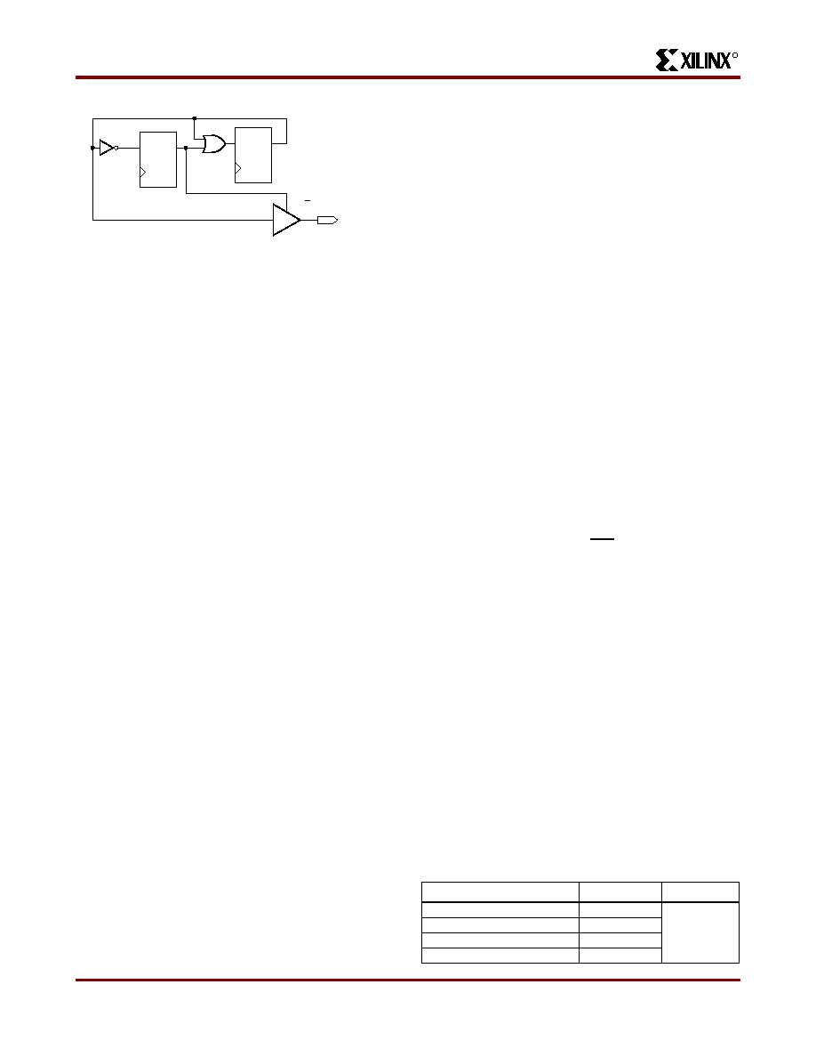
Output
Connected
to CCLK
OE/T
0
1
0
.
0
1
.
Reset
X5223
etc
Active Low Output
Active High Output
Figure 22: CCLK Generation for XC3000 Master
Driving an XC5200-Series Slave
Table 11: XC5200 Bitstream Format
Data Type
Value
Occurrences
Fill Byte
11111111
Once per bit-
stream
Preamble
11110010
Length Counter
COUNT(23:0)
Fill Byte
11111111
相关PDF资料 |
PDF描述 |
|---|---|
| XC5206-3BG225C | Field Programmable Gate Arrays |
| XC5206-3BG352C | Field Programmable Gate Arrays |
| XC5206-3HQ208C | Field Programmable Gate Arrays |
| XC5206-3HQ240C | Field Programmable Gate Arrays |
| XC5206-3PG156C | Field Programmable Gate Arrays |
相关代理商/技术参数 |
参数描述 |
|---|---|
| XC5204-6TQ144I | 制造商:Xilinx 功能描述: |
| XC5204-6TQ176C | 制造商:XILINX 制造商全称:XILINX 功能描述:Field Programmable Gate Arrays |
| XC5204-6VQ100C | 功能描述:IC FPGA 120 CLB'S 100-VQFP RoHS:否 类别:集成电路 (IC) >> 嵌入式 - FPGA(现场可编程门阵列) 系列:XC5200 产品变化通告:XC4000(E,L) Discontinuation 01/April/2002 标准包装:24 系列:XC4000E/X LAB/CLB数:100 逻辑元件/单元数:238 RAM 位总计:3200 输入/输出数:80 门数:3000 电源电压:4.5 V ~ 5.5 V 安装类型:表面贴装 工作温度:-40°C ~ 100°C 封装/外壳:120-BCBGA 供应商设备封装:120-CPGA(34.55x34.55) |
| XC5204-6VQ100I | 制造商:Xilinx 功能描述: |
| XC5204-6VQ64C | 制造商:XILINX 制造商全称:XILINX 功能描述:Field Programmable Gate Arrays |
发布紧急采购,3分钟左右您将得到回复。