- 您现在的位置:买卖IC网 > PDF目录1975 > XR17V352IB113-F (Exar Corporation)IC UART PCIE 256B DUAL 113FPBGA PDF资料下载
参数资料
| 型号: | XR17V352IB113-F |
| 厂商: | Exar Corporation |
| 文件页数: | 34/64页 |
| 文件大小: | 0K |
| 描述: | IC UART PCIE 256B DUAL 113FPBGA |
| 产品培训模块: | PCIe UARTs |
| 标准包装: | 260 |
| 特点: | * |
| 通道数: | 2,DUART |
| FIFO's: | 256 字节 |
| 规程: | RS485 |
| 电源电压: | 3.3V |
| 带自动流量控制功能: | 是 |
| 带IrDA 编码器/解码器: | 是 |
| 带故障启动位检测功能: | 是 |
| 带调制解调器控制功能: | 是 |
| 安装类型: | 表面贴装 |
| 封装/外壳: | 113-LFBGA |
| 供应商设备封装: | 113-FPBGA |
| 包装: | 托盘 |
| 其它名称: | 1016-1471 XR17V352IB113-F-ND |
第1页第2页第3页第4页第5页第6页第7页第8页第9页第10页第11页第12页第13页第14页第15页第16页第17页第18页第19页第20页第21页第22页第23页第24页第25页第26页第27页第28页第29页第30页第31页第32页第33页当前第34页第35页第36页第37页第38页第39页第40页第41页第42页第43页第44页第45页第46页第47页第48页第49页第50页第51页第52页第53页第54页第55页第56页第57页第58页第59页第60页第61页第62页第63页第64页
XR17V352
4
HIGH PERFORMANCE DUAL PCI EXPRESS UART
REV. 1.0.3
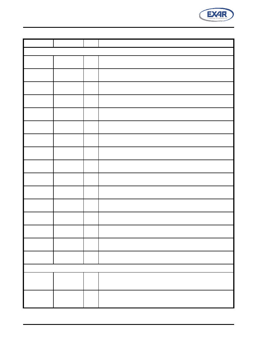
MPIO SIGNALS
MPIO0
A2
I/O
Multi-purpose input/output 0. The function of this pin is defined thru the Con-
figuration Register MPIOSEL, MPIOLVL, MPIOINV, MPIO3T and MPIOINT
MPIO1
C3
I/O
Multi-purpose input/output 1. The function of this pin is defined thru the Con-
figuration Register MPIOSEL, MPIOLVL, MPIOINV, MPIO3T and MPIOINT.
MPIO2
B2
I/O
Multi-purpose input/output 2. The function of this pin is defined thru the Con-
figuration Register MPIOSEL, MPIOLVL, MPIOINV, MPIO3T and MPIOINT.
MPIO3
B1
I/O
Multi-purpose input/output 3. The function of this pin is defined thru the Con-
figuration Register MPIOSEL, MPIOLVL, MPIOINV, MPIO3T and MPIOINT.
MPIO4
C2
I/O
Multi-purpose input/output 4. The function of this pin is defined thru the Con-
figuration Register MPIOSEL, MPIOLVL, MPIOINV, MPIO3T and MPIOINT.
MPIO5
D3
I/O
Multi-purpose input/output 5. The function of this pin is defined thru the Con-
figuration Register MPIOSEL, MPIOLVL, MPIOINV, MPIO3T and MPIOINT.
MPIO6
C1
I/O
Multi-purpose input/output 6. The function of this pin is defined thru the Con-
figuration Register MPIOSEL, MPIOLVL, MPIOINV, MPIO3T and MPIOINT.
MPIO7
K1
I/O
Multi-purpose input/output 7. The function of this pin is defined thru the Con-
figuration Register MPIOSEL, MPIOLVL, MPIOINV, MPIO3T and MPIOINT.
MPIO8
K2
I/O
Multi-purpose input/output 8. The function of this pin is defined thru the Con-
figuration Register MPIOSEL, MPIOLVL, MPIOINV, MPIO3T and MPIOINT
MPIO9
J3
I/O
Multi-purpose input/output 9. The function of this pin is defined thru the Con-
figuration Register MPIOSEL, MPIOLVL, MPIOINV, MPIO3T and MPIOINT.
MPIO10
L2
I/O
Multi-purpose input/output 10. The function of this pin is defined thru the Con-
figuration Register MPIOSEL, MPIOLVL, MPIOINV, MPIO3T and MPIOINT.
MPIO11
K3
I/O
Multi-purpose input/output 11. The function of this pin is defined thru the Con-
figuration Register MPIOSEL, MPIOLVL, MPIOINV, MPIO3T and MPIOINT.
MPIO12
L3
I/O
Multi-purpose input/output 12. The function of this pin is defined thru the Con-
figuration Register MPIOSEL, MPIOLVL, MPIOINV, MPIO3T and MPIOINT.
MPIO13
J4
I/O
Multi-purpose input/output 13. The function of this pin is defined thru the Con-
figuration Register MPIOSEL, MPIOLVL, MPIOINV, MPIO3T and MPIOINT.
MPIO14
K4
I/O
Multi-purpose input/output 14. The function of this pin is defined thru the Con-
figuration Register MPIOSEL, MPIOLVL, MPIOINV, MPIO3T and MPIOINT.
MPIO15
L5
I/O
Multi-purpose input/output 15. The function of this pin is defined thru the Con-
figuration Register MPIOSEL, MPIOLVL, MPIOINV, MPIO3T and MPIOINT.
EEPROM SIGNALS
EECK
J7
O
Serial clock to EEPROM. An internal clock of CLK divide by 256 is used for
reading the vendor and sub-vendor ID during power up or reset. However, it
can be manually clocked thru the Configuration Register REGB.
EECS
K8
O
Chip select to a EEPROM device like 93C46. It is manually selectable thru
the Configuration Register REGB. Requires a pull-up 4.7K ohm resistor for
external sensing of EEPROM during power up.
PIN DESCRIPTIONS
NAME
PIN #TYPE
DESCRIPTION
相关PDF资料 |
PDF描述 |
|---|---|
| XR17V354IB176-F | IC UART PCIE 256B QUAD 176FPBGA |
| XR17V358IB176-F | IC UART PCIE OCTAL 176FPBGA |
| XR19L200IL32-F | IC UART/TXRX RS232 32QFN |
| XR19L202IL48-F | IC UART/TXRX RS232 48QFN |
| XR19L210IL40-F | IC UART/TXRX RS232 40QFN |
相关代理商/技术参数 |
参数描述 |
|---|---|
| XR17V354 | 制造商:EXAR 制造商全称:EXAR 功能描述:HIGH PERFORMANCE QUAD PCI-EXPRESS UART |
| XR17V354IB-0A-EVB | 功能描述:界面开发工具 Eval Board for XR17V354IB-0A RoHS:否 制造商:Bourns 产品:Evaluation Boards 类型:RS-485 工具用于评估:ADM3485E 接口类型:RS-485 工作电源电压:3.3 V |
| XR17V354IB176-F | 功能描述:UART 接口集成电路 4 Channel PCIe UART w/256 Byte FIFO RoHS:否 制造商:Texas Instruments 通道数量:2 数据速率:3 Mbps 电源电压-最大:3.6 V 电源电压-最小:2.7 V 电源电流:20 mA 最大工作温度:+ 85 C 最小工作温度:- 40 C 封装 / 箱体:LQFP-48 封装:Reel |
| XR17V354IB-E4-EVB | 功能描述:界面开发工具 Eval Board for XR17V354IB-E4 RoHS:否 制造商:Bourns 产品:Evaluation Boards 类型:RS-485 工具用于评估:ADM3485E 接口类型:RS-485 工作电源电压:3.3 V |
| XR17V354IB-E8-EVB | 功能描述:界面开发工具 Eval Board for XR17V354IB-E8 RoHS:否 制造商:Bourns 产品:Evaluation Boards 类型:RS-485 工具用于评估:ADM3485E 接口类型:RS-485 工作电源电压:3.3 V |
发布紧急采购,3分钟左右您将得到回复。