参数资料
| 型号: | XRT82L24AIV-F |
| 厂商: | Exar Corporation |
| 文件页数: | 36/39页 |
| 文件大小: | 0K |
| 描述: | IC LIU E1 QAUD 100TQFP |
| 标准包装: | 90 |
| 类型: | 线路接口装置(LIU) |
| 驱动器/接收器数: | 4/4 |
| 规程: | E1 |
| 电源电压: | 3.135 V ~ 3.465 V |
| 安装类型: | 表面贴装 |
| 封装/外壳: | 100-LQFP |
| 供应商设备封装: | 100-TQFP(14x14) |
| 包装: | 托盘 |
| 其它名称: | XRT82L24AIV-F-ND |
第1页第2页第3页第4页第5页第6页第7页第8页第9页第10页第11页第12页第13页第14页第15页第16页第17页第18页第19页第20页第21页第22页第23页第24页第25页第26页第27页第28页第29页第30页第31页第32页第33页第34页第35页当前第36页第37页第38页第39页
XRT82L24A
á
QUAD E1 LINE TRANSCEIVER WITH CLOCK RECOVERY AND JITTER ATTENUATOR
REV. 1.1.2
4
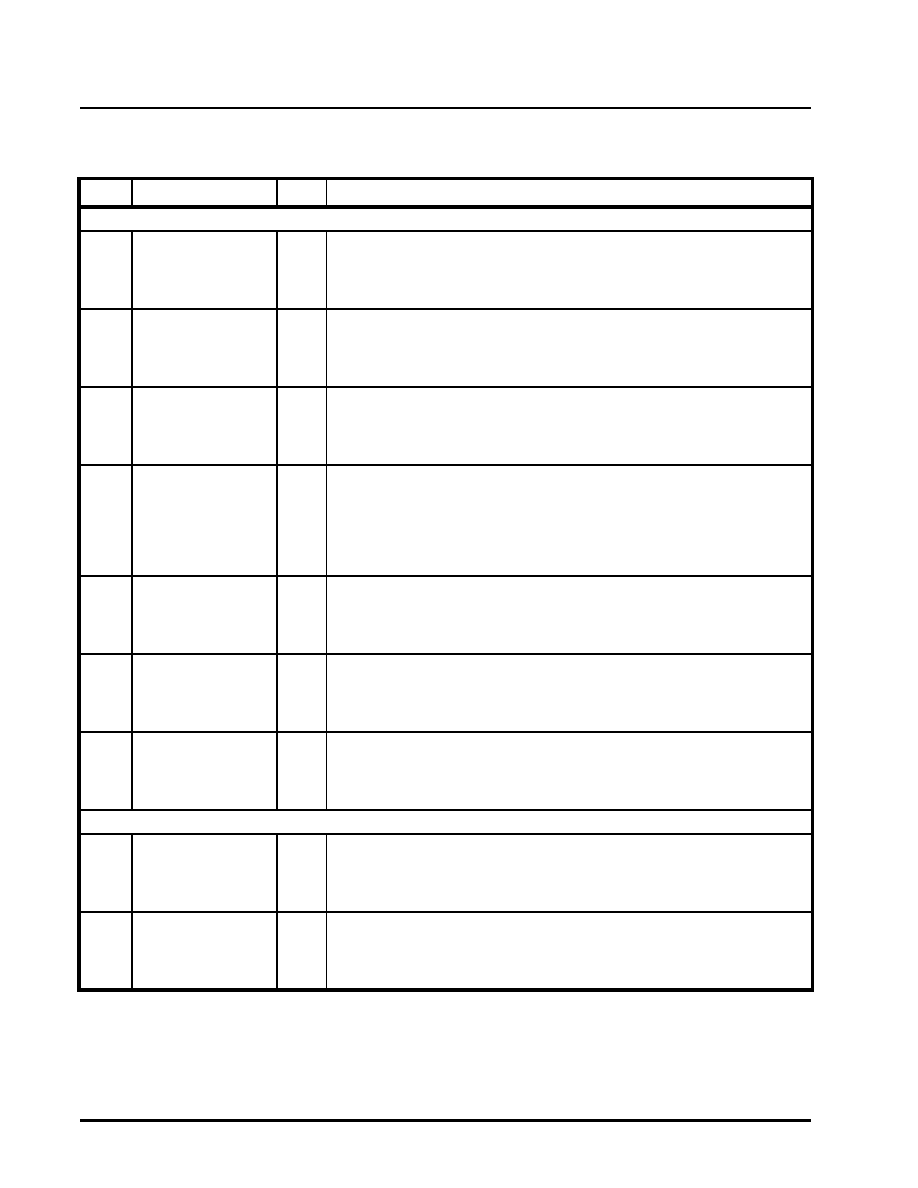
PIN DESCRIPTION
PIN DESCRIPTIONS
PIN #NAME
TYPE
DESCRIPTION
RECEIVER SECTIONS
1
25
51
75
RxCLK_0/RZData_0
RxCLK_1/RZData_1
RxCLK_2/RZData_2
RxCLK_3/RZData_3
O
Receiver_n Clock Output
Rzdata Output:
In Data Slicer Mode, (register 0, bit 7 = 1) or in Hardware Mode when MClk is
absent, this signal is OR-ed RZdata after the slicers.
2
24
52
74
RxLOS_0
RxLOS_1
RxLOS_2
RxLOS_3
O
Receiver_n Loss of Signal. This signal is asserted "High" to indicate loss of
signal at the receive input.
100
26
50
76
RxPOS_0/RData_0
RxPOS_1/RData_1
RxPOS_2/RData_2
RxPOS_3/RData_3
O
Receiver 1 Positive Data Output:
In dual-rail mode, this signal is the receive P-rail output data.
Receiver 1 NRZ Data Output:
In single-rail mode, this signal is the receive output data.
99
27
49
77
RxNEG_0/LCV_0
RxNEG_1/LCV_1
RxNEG_2/LCV_2
RxNEG_3/LCV_3
O
Receiver_n Negative Data Output:
In dual-rail mode, n-rail data are sent to the framer.
Line Code Violation Output - Channel_n:
In single-rail mode, this signal output "High" for one receive clock cycle to indi-
cate a code violation is detected in the received data. If AMI coding is selected,
every bipolar violation received will cause this pin to go "High".
95
31
45
81
RRing_0
RRing_1
RRing_2
RRing_3
I
Receiver_n Differential Negative Input.
94
32
44
82
RTIP_0
RTIP_1
RTIP_2
RTIP_3
I
Receiver_n Differential Positive Input.
67
RXMUTE
I
Hardware Mode, Receive Muting:
Connect this pin "High" to mute RxPOS/RxNEG output to a low state upon
receive LOS condition to prevent data chattering. Connect Low to disable mut-
ing function.
TRANSMITTER SECTIONS
3
23
53
73
TxNEG_0
TxNEG_1
TxNEG_2
TxNEG_3
I
Transmitter_n Negative NRZ Data Input. In dual-rail mode, this signal is the n-
rail input data for transmitter 0. In single-rail mode, this pin can be left uncon-
nected.
4
22
54
72
TxPOS_0/TData_0
TxPOS_1/TData_1
TxPOS_2/TData_2
TxPOS_3/TData_3
I
Transmitter_n Positive Data Input. In dual-rail mode, this signal is the p-rail
input data for transmitter 0.
Transmitter 0 Data Input. In single-rail mode, this pin is used as the NRZ input
data for transmitter 0.
相关PDF资料 |
PDF描述 |
|---|---|
| XRT83D10IW | IC LIU T1/E1 SGL 28SOJ |
| XRT83L30IV-F | IC LIU LH/SH T1/E1 SGL 64TQFP |
| XRT83L314IB-L | IC LIU T1/E1/J1 14CH 304TBGA |
| XRT83L34IV-F | IC LIU T1/E1/J1 QUAD 128TQFP |
| XRT83L38IB-F | IC LIU T1/E1/J1 OCTAL 225BGA |
相关代理商/技术参数 |
参数描述 |
|---|---|
| XRT82L24ES | 功能描述:界面开发工具 Evaluation Board for XRT82L24 Series RoHS:否 制造商:Bourns 产品:Evaluation Boards 类型:RS-485 工具用于评估:ADM3485E 接口类型:RS-485 工作电源电压:3.3 V |
| XRT82L24IV | 制造商:EXAR 制造商全称:EXAR 功能描述:QUAD E1 LINE TRANSCEIVER WITH CLOCK RECOVERY AND JITTER ATTENUATOR |
| XRT82L34IV | 制造商:未知厂家 制造商全称:未知厂家 功能描述:Interface IC |
| XRT83D10 | 制造商:EXAR 制造商全称:EXAR 功能描述:SINGLE CHANNEL DS1/CEPT LINE INTERFACE UNIT |
| XRT83D10ES | 功能描述:外围驱动器与原件 - PCI 1 CHT1/E1LIUSH RoHS:否 制造商:PLX Technology 工作电源电压: 最大工作温度: 安装风格:SMD/SMT 封装 / 箱体:FCBGA-1156 封装:Tray |
发布紧急采购,3分钟左右您将得到回复。