- 您现在的位置:买卖IC网 > PDF目录1773 > A4490EES-T (Allegro Microsystems Inc)IC REG BUCK ADJ 1.5A TRPL 20QFN PDF资料下载
参数资料
| 型号: | A4490EES-T |
| 厂商: | Allegro Microsystems Inc |
| 文件页数: | 10/17页 |
| 文件大小: | 0K |
| 描述: | IC REG BUCK ADJ 1.5A TRPL 20QFN |
| 标准包装: | 92 |
| 类型: | 降压(降压) |
| 输出类型: | 可调式 |
| 输出数: | 3 |
| 输出电压: | 可调 |
| 输入电压: | 4.5 V ~ 34 V |
| PWM 型: | 电流模式 |
| 频率 - 开关: | 550kHz |
| 电流 - 输出: | 1.5A |
| 同步整流器: | 无 |
| 工作温度: | -40°C ~ 85°C |
| 安装类型: | 表面贴装 |
| 封装/外壳: | 20-WFQFN 裸露焊盘 |
| 包装: | 管件 |
| 供应商设备封装: | 20-QFN 裸露焊盘(4x4) |
| 配用: | 620-1388-ND - BOARD EVAL FOR A4490 |
| 其它名称: | A4490SES-T A4490SES-T-ND |
�� �
�
�A4490�
�Triple� Output� Step-Down� Switching� Regulator�
�The� bias� current,� I� BIAS� ,� flowing� out� of� the� FB1� node� into� R2,� will�
�introduce� a� small� voltage� offset� to� the� output.�
�Enable� Each� regulator� channel� can� be� individually� enabled� via�
�the� corresponding� ENBx� pin.� If� any� channel� is� required� to� start-�
�up� automatically� after� the� VBB� voltage� is� applied,� that� particu-�
�lar� channel� should� have� the� ENB� pin� tied� to� the� VBB� rail� via� a�
�pullup� resistor.�
�This� resistor� should� be� selected� to� limit� the� current� to� less� than�
�the� maximum� specified� value,� 1� mA.� This� prevents� the� internal�
�protection� clamps� from� turning� on.� It� is� recommended� that� a�
�100� k� Ω� pull-up� resistor� be� used.� This� would� ensure� the� current�
�remains� below� the� maximum� value� when� V� BB� =� 36� V.�
�Soft� Start� Each� regulator� channel� contains� a� soft� start� circuit.� A�
�soft� start� cycle� is� initiated� when� the� appropriate� regulator� enable�
�input� is� set� to� high;� the� V� BB� ,� charge� pump,� and� bias� supply� volt-�
�ages� are� above� the� minimum� values;� and� no� thermal� shutdown�
�condition� exists.� Note� that� an� overload� or� short� circuit� will� not�
�cause� a� soft� start� cycle,� unless� a� thermal� shutdown� event� occurs.�
�During� a� soft� start� cycle,� the� reference� voltage� is� ramped� from�
�0� to� 0.8� V� typical,� which� in� turn� forces� the� current� demand� signal�
�to� increase� in� a� linear� fashion.�
�Shutdown� All� converter� channels� are� disabled� in� the� event� of�
�either� a� thermal� shutdown� event� or� an� undervoltage� on� VBB�
�(V� BBUV(sd)� or� V� BBCPUV(sd)� ).�
�As� soon� as� the� above� fault� conditions� have� been� removed,� and�
�assuming� the� ENB� inputs� are� enabled,� the� appropriate� channels�
�will� auto-restart� under� control� of� the� soft� start.�
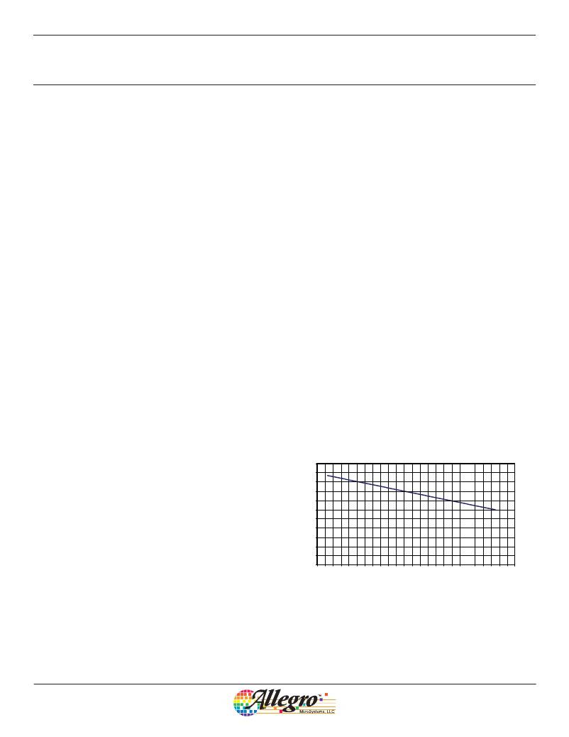
�Current� Limit� The� typical� peak� current� limit� for� each� channel� is�
�specified� as� 2.5� A� minimum,� with� a� duty� cycle� of� 0.9.� The� mini-�
�mum� current� limit� occurs� at� maximum� duty� cycle� (0.9),� because�
�the� slope� compensation� has� a� maximum� effect� under� this� condi-�
�tion.� As� the� duty� cycle� reduces,� the� current� limit� increases.� This�
�means� for� applications� that� operate� with� a� narrow� duty� cycle,� it� is�
�possible� to� operate� with� a� load� current� greater� than� 2.0� A.�
�Figure� 3� illustrates� the� typical� peak� current� limit� versus� duty�
�to� check� the� implications� on� the� thermal� performance.� See� the�
�Thermal� Considerations� section.�
�Component� Selection�
�Inductor� The� inductance� value,� L,� determines� the� ripple� current.�
�It� is� important� to� ensure� that� the� minimum� current� limit� is� not�
�exceeded� under� worst-case� conditions:� V� BB� (min),� I� LOAD� (max),�
�f� SW� (min),� and� L(min).�
�It� is� recommended� that� gapped� ferrite� solutions� be� used� as�
�opposed� to� powdered� iron� solutions,� the� latter� of� which� exhibit�
�relatively� high� core� losses� that� can� have� a� large� impact� on� long�
�term� reliability.�
�Inductors� are� typically� specified� at� two� current� levels,� rms� cur-�
�rent� and� saturation� current.� With� regard� to� the� rms� current,� it� is�
�important� to� understand� how� the� rms� current� level� is� specified,�
�in� terms� of� ambient� temperature.� Some� manufacturers� quote� an�
�ambient� only,� whilst� others� quote� a� temperature� that� includes� a�
�self-induced� temperature� rise.� For� example,� if� an� inductor� is� rated�
�for� 85°C� and� includes� a� self-induced� temperature� rise� of� 25°C�
�at� maximum� load,� then� the� inductor� cannot� be� safely� operated�
�beyond� an� ambient� temperature� of� 60°C� at� full� load.� The� rms� cur-�
�rent� can� be� assumed� to� be� simply� the� maximum� load� current,� with�
�perhaps� some� margin� to� allow� for� overloads,� and� so� forth.�
�The� first� stage� of� determining� the� inductor� value� is� to� specify� a�
�peak-to-peak� ripple� current� of� typically� about� 20%� to� 25%� of� the�
�maximum� load.�
�5.0�
�4.5�
�4.0�
�3.5�
�3.0�
�2.5�
�2.0�
�1.5�
�0.5�
�1.0�
�0.5�
�0�
�cycle.� For� example,� it� is� possible� to� operate� with� a� peak� current�
�0�
�20�
�40�
�60�
�80�
�100�
�limit� of� 3.75� A� with� a� duty� cycle� of� 0.3.�
�As� well� as� ensuring� the� peak� current� limit� is� not� exceeded,� under�
�worst� case� load� and� input� voltage� conditions,� it� is� also� important�
�Duty� Cycle� (%)�
�Figure� 3.� Current� limit� versus� duty� cycle�
�Allegro� MicroSystems,� LLC�
�115� Northeast� Cutoff�
�Worcester,� Massachusetts� 01615-0036� U.S.A.�
�1.508.853.5000;� www.allegromicro.com�
�10�
�相关PDF资料 |
PDF描述 |
|---|---|
| A4491EESTR-T | IC REG BUCK ADJ 2.2A TRPL 20QFN |
| A4931MET-T | IC DC MOTOR PREDRIVER 3PH 28QFN |
| A4934GLPTR-T | IC BLDC DVR 3PHASE 16-ETSSOP |
| A4936METTR-T | IC DC MOTOR PREDRIVER 3PH 32QFN |
| A4938EETTR-T | IC DC MOTOR PREDRIVER 3PH 28-QFN |
相关代理商/技术参数 |
参数描述 |
|---|---|
| A4490EESTRT | 制造商:ALLEGRO 功能描述:Pb Free |
| A4490EESTR-T | 功能描述:IC REG BUCK ADJ 1.5A TRPL 20QFN RoHS:是 类别:集成电路 (IC) >> PMIC - 稳压器 - DC DC 开关稳压器 系列:- 标准包装:250 系列:- 类型:降压(降压) 输出类型:固定 输出数:1 输出电压:1.2V 输入电压:2.05 V ~ 6 V PWM 型:电压模式 频率 - 开关:2MHz 电流 - 输出:500mA 同步整流器:是 工作温度:-40°C ~ 85°C 安装类型:表面贴装 封装/外壳:6-UFDFN 包装:带卷 (TR) 供应商设备封装:6-SON(1.45x1) 产品目录页面:1032 (CN2011-ZH PDF) 其它名称:296-25628-2 |
| A4491 | 制造商:ALLEGRO 制造商全称:Allegro MicroSystems 功能描述:Designed to provide the power supply requirements of printers, office automation, industrial, and portable equipment, the A4491 provides three high current, |
| A4491EESTR-T | 功能描述:IC REG BUCK ADJ 2.2A TRPL 20QFN RoHS:是 类别:集成电路 (IC) >> PMIC - 稳压器 - DC DC 开关稳压器 系列:- 标准包装:50 系列:- 类型:升压(升压) 输出类型:可调式 输出数:1 输出电压:5 V ~ 25 V 输入电压:2.3 V ~ 5.5 V PWM 型:电流模式 频率 - 开关:600kHz,1.2MHz 电流 - 输出:1A 同步整流器:无 工作温度:-40°C ~ 85°C 安装类型:表面贴装 封装/外壳:8-TSSOP,8-MSOP(0.118",3.00mm 宽) 包装:管件 供应商设备封装:8-MSOP |
| A4492 | 制造商:ALLEGRO 制造商全称:Allegro MicroSystems 功能描述:Designed to provide the power supply requirements for automotive applications, the A4492 provides three high current, high performance, switching regulator outputs with independent soft start. |
发布紧急采购,3分钟左右您将得到回复。