- 您现在的位置:买卖IC网 > PDF目录10744 > AD7730BRU-REEL7 (Analog Devices Inc)IC ADC TRANSDUCER BRIDGE 24TSSOP PDF资料下载
参数资料
| 型号: | AD7730BRU-REEL7 |
| 厂商: | Analog Devices Inc |
| 文件页数: | 35/53页 |
| 文件大小: | 0K |
| 描述: | IC ADC TRANSDUCER BRIDGE 24TSSOP |
| 标准包装: | 1,000 |
| 位数: | 24 |
| 通道数: | 1 |
| 功率(瓦特): | 125mW |
| 电压 - 电源,模拟: | 4.75 V ~ 5.25 V |
| 电压 - 电源,数字: | 2.7 V ~ 5.25 V |
| 封装/外壳: | 24-TSSOP(0.173",4.40mm 宽) |
| 供应商设备封装: | 24-TSSOP |
| 包装: | 带卷 (TR) |
| 配用: | EVAL-AD7730LEBZ-ND - BOARD EVALUATION FOR AD7730 EVAL-AD7730EBZ-ND - BOARD EVAL FOR AD7730 |
第1页第2页第3页第4页第5页第6页第7页第8页第9页第10页第11页第12页第13页第14页第15页第16页第17页第18页第19页第20页第21页第22页第23页第24页第25页第26页第27页第28页第29页第30页第31页第32页第33页第34页当前第35页第36页第37页第38页第39页第40页第41页第42页第43页第44页第45页第46页第47页第48页第49页第50页第51页第52页第53页
AD7730/AD7730L
–40–
APPLICATIONS
The on-chip PGA allows the AD7730 to handle analog input
voltage ranges as low as 10 mV full scale. This allows the user to
connect a transducer directly to the input of the AD7730. The
AD7730 is primarily targeted for weigh-scale and load-cell
applications. The majority of the applications have a strain-
gage transducer whose resistance changes when subjected to
mechanical stress. Normally, the gages are configured in a
Wheatstone bridge arrangement. The strain gage is a passive
device and requires an excitation voltage (or in some cases a
current) to derive a voltage output. Two types of voltage excita-
tion can be provided for the bridge: dc excitation or ac excita-
tion. These are discussed in the following sections. While the
desire in most applications is to provide a single supply solution
(something that is aided by the AD7730’s single supply capabil-
ity), some applications provide a bipolar excitation voltage in
order to increase the output voltage from the bridge. In such
cases, the input voltage applied to the AD7730 can be slightly
negative with respect to ground. Figure 23 shows how to config-
ure the AD7730 to handle this type of input signal.
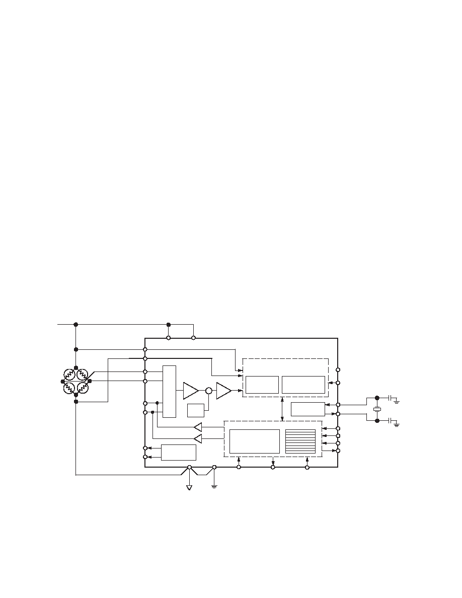
DC Excitation of Bridge
In dc-excitation applications, the excitation voltage provided for
the bridge is a fixed dc voltage. Connections between the AD7730
and the bridge are very straightforward in this type of applica-
tion as illustrated in Figure 23. The bridge configuration shown
is a six-lead configuration with separate return leads for the
reference lines. This allows a force/sense effect on the load cell
excitation voltage, eliminating voltage drops caused by the exci-
tation current flowing through the lead resistances. In applica-
tions where the lead lengths are short, a four-wire configuration
can be used with the excitation voltage and analog ground con-
nected local to the AD7730’s REF IN(+) and REF IN(–) termi-
nals. Illustrating a major advantage of the AD7730, the 5 V
excitation voltage for the bridge can be used directly as the refer-
ence voltage for the AD7730, eliminating the need for precision
matched resistors in generating a scaled-down reference.
The application is a ratiometric one with variations in the exci-
tation voltage being reflected in variations in the analog input
voltage and reference voltage of the AD7730. Because the
AD7730 is a truly ratiometric part, with the reference voltage
and excitation voltages equal, it is possible to evaluate its total
excitation voltage rejection. This is unlike other converters
which give a separate indication of the rejection of reference,
analog inputs and power supply. The combined (total) rejection
for the AD7730 when moving the excitation voltage (which was
also the power supply voltage) was better than 115 dB when
evaluated with a load cell simulator.
Drift considerations are a primary concern for load cell applica-
tions. It is recommended for these applications that the AD7730
is operated in CHOP mode to accrue the benefits of the excel-
lent drift performance of the part in CHOP mode. A common
source of unwanted drift effects are parasitic thermocouples.
Thermocouple effects are generated every time there is a junc-
tion of two dissimilar metals. All components in the signal path
should be chosen to minimize thermocouple effects. IC sockets
and link options should be avoided as much as possible. While
it is impossible to remove all thermocouple effects, attempts should
be made to equalize the thermocouples on each leg of the differen-
tial input to minimize the differential voltage generated.
Figure 23. Typical Connections for DC-Excited Bridge Application
SIGMA-
DELTA
MODULATOR
AVDD
DVDD
AD7730
6-BIT
DAC
SERIAL INTERFACE
AND CONTROL LOGIC
REGISTER BANK
CLOCK
GENERATION
PROGRAMMABLE
DIGITAL
FILTER
SIGMA-DELTA A/D CONVERTER
BUFFER
PGA
AIN2(+)/D1
AIN2(–)/D0
ACX
STANDBY
SYNC
MCLK IN
MCLK OUT
SCLK
CS
DIN
DOUT
RESET
RDY
POL
DGND
AGND
MUX
AC
EXCITATION
CLOCK
CALIBRATION
MICROCONTROLLER
+
IN+
OUT–
IN–
OUT+
REF IN(+)
REF IN(–)
AIN1(+)
AIN1(–)
EXCITATION VOLTAGE = +5V
+/–
REV. B
相关PDF资料 |
PDF描述 |
|---|---|
| AD7730BRU-REEL | IC ADC TRANSDUCER BRIDGE 24TSSOP |
| AD7730BR-REEL | IC ADC TRANSDUCER BRIDGE 24-SOIC |
| AD7730LBR-REEL7 | IC ADC TRANSDUCER BRIDGE 24SOIC |
| XRD9824ACD-F | IC 14B CCD/CIS SIG PROC 20SOIC |
| MAX933CSA+ | IC COMPARATOR W/REF 8-SOIC |
相关代理商/技术参数 |
参数描述 |
|---|---|
| AD7730BRUZ | 功能描述:IC ADC TRANSDUCER BRIDGE 24TSSOP RoHS:是 类别:集成电路 (IC) >> 数据采集 - 模拟前端 (AFE) 系列:- 产品培训模块:Lead (SnPb) Finish for COTS Obsolescence Mitigation Program 标准包装:2,500 系列:- 位数:- 通道数:2 功率(瓦特):- 电压 - 电源,模拟:3 V ~ 3.6 V 电压 - 电源,数字:3 V ~ 3.6 V 封装/外壳:32-VFQFN 裸露焊盘 供应商设备封装:32-QFN(5x5) 包装:带卷 (TR) |
| AD7730BRUZ-REEL | 功能描述:IC ADC BRIDGE TRANSDUCER 24TSSOP RoHS:是 类别:集成电路 (IC) >> 数据采集 - 模拟前端 (AFE) 系列:- 产品培训模块:Lead (SnPb) Finish for COTS Obsolescence Mitigation Program 标准包装:2,500 系列:- 位数:- 通道数:2 功率(瓦特):- 电压 - 电源,模拟:3 V ~ 3.6 V 电压 - 电源,数字:3 V ~ 3.6 V 封装/外壳:32-VFQFN 裸露焊盘 供应商设备封装:32-QFN(5x5) 包装:带卷 (TR) |
| AD7730BRUZ-REEL7 | 功能描述:IC ADC BRIDGE TRANSDUCER 24TSSOP RoHS:是 类别:集成电路 (IC) >> 数据采集 - 模拟前端 (AFE) 系列:- 产品培训模块:Lead (SnPb) Finish for COTS Obsolescence Mitigation Program 标准包装:2,500 系列:- 位数:- 通道数:2 功率(瓦特):- 电压 - 电源,模拟:3 V ~ 3.6 V 电压 - 电源,数字:3 V ~ 3.6 V 封装/外壳:32-VFQFN 裸露焊盘 供应商设备封装:32-QFN(5x5) 包装:带卷 (TR) |
| AD7730BRZ | 功能描述:IC ADC BRIDGE TRANSDUCER 24-SOIC RoHS:是 类别:集成电路 (IC) >> 数据采集 - 模拟前端 (AFE) 系列:- 产品培训模块:Lead (SnPb) Finish for COTS Obsolescence Mitigation Program 标准包装:2,500 系列:- 位数:- 通道数:2 功率(瓦特):- 电压 - 电源,模拟:3 V ~ 3.6 V 电压 - 电源,数字:3 V ~ 3.6 V 封装/外壳:32-VFQFN 裸露焊盘 供应商设备封装:32-QFN(5x5) 包装:带卷 (TR) |
| AD7730BRZ | 制造商:Analog Devices 功能描述:IC, ADC, 24BIT, 1.2KSPS, SOIC-24 |
发布紧急采购,3分钟左右您将得到回复。