- 您现在的位置:买卖IC网 > PDF目录10541 > AD7854LARSZ (Analog Devices Inc)IC ADC 12BIT PARALLEL LP 28SSOP PDF资料下载
参数资料
| 型号: | AD7854LARSZ |
| 厂商: | Analog Devices Inc |
| 文件页数: | 13/28页 |
| 文件大小: | 0K |
| 描述: | IC ADC 12BIT PARALLEL LP 28SSOP |
| 标准包装: | 47 |
| 位数: | 12 |
| 采样率(每秒): | 100k |
| 数据接口: | 并联 |
| 转换器数目: | 2 |
| 功率耗散(最大): | 30mW |
| 电压电源: | 模拟和数字 |
| 工作温度: | -40°C ~ 85°C |
| 安装类型: | 表面贴装 |
| 封装/外壳: | 28-SSOP(0.209",5.30mm 宽) |
| 供应商设备封装: | 28-SSOP |
| 包装: | 管件 |
| 输入数目和类型: | 1 个伪差分,单极;1 个伪差分,双极 |
第1页第2页第3页第4页第5页第6页第7页第8页第9页第10页第11页第12页当前第13页第14页第15页第16页第17页第18页第19页第20页第21页第22页第23页第24页第25页第26页第27页第28页
AD7854/AD7854L
–20–
REV. B
CALIBRATION SECTION
Calibration Overview
The automatic calibration that is performed on power-up
ensures that the calibration options covered in this section are
not required in a significant number of applications. A calibration
does not have to be initiated unless the operating conditions
change (CLKIN frequency, analog input mode, reference volt-
age, temperature, and supply voltages). The AD7854/AD7854L
has a number of calibration features that may be required in
some applications, and there are a number of advantages in per-
forming these different types of calibration. First, the internal
errors in the ADC can be reduced significantly to give superior
dc performance; and second, system offset and gain errors can
be removed. This allows the user to remove reference errors
(whether it be internal or external reference) and to make use of
the full dynamic range of the AD7854/AD7854L by adjusting
the analog input range of the part for a specific system.
There are two main calibration modes on the AD7854/AD7854L,
self-calibration and system calibration. There are various op-
tions in both self-calibration and system calibration as outlined
previously in Table III. All the calibration functions are initi-
ated by writing to the control register and setting the STCAL
bit to 1.
The duration of each of the different types of calibration is given
in Table IX for the AD7854 with a 4 MHz master clock. These
calibration times are master clock dependent. Therefore the
calibration times for the AD7854L (CLKIN = 1.8 MHz) are
larger than those quoted in Table VIII.
Table VIII. Calibration Times (AD7854 with 4 MHz CLKIN)
Type of Self-Calibration or System Calibration
Time
Full
31.25 ms
Gain + Offset
6.94 ms
Offset
3.47 ms
Gain
3.47 ms
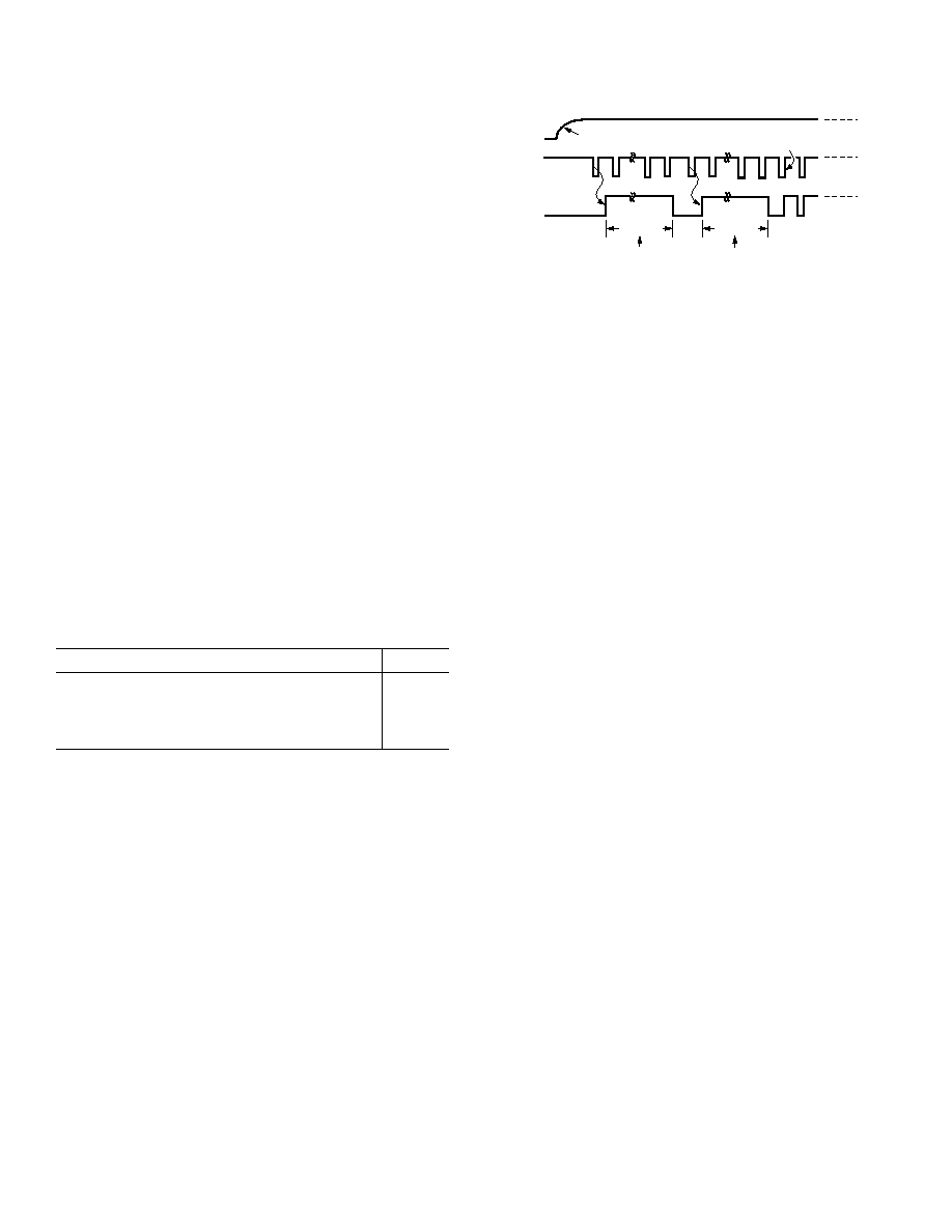
Automatic Calibration on Power-On
The automatic calibration on power-on is initiated by the first
CONVST pulse after the AV
DD and DVDD power on. From the
CONVST pulse the part internally sets a 32/72 ms (4 MHz/
1.8 MHz CLKIN) timeout. This time is large enough to ensure
that the internal reference has settled before the calibration is
performed. However, if an external reference is being used, this
reference must have stabilized before the automatic calibration
is initiated. This first
CONVST pulse also triggers the BUSY
signal high, and once the 32/72 ms has elapsed, the BUSY signal
goes low. At this point the next
CONVST pulse that is applied
initiates the automatic full self-calibration. This
CONVST pulse
again triggers the BUSY signal high, and after 32/72 ms (4 MHz/
1.8 MHz CLKIN), the calibration is completed and the BUSY
signal goes low. This timing arrangement is shown in Figure 28.
The times in Figure 28 assume a 4 MHz /1.8 MHz CLKIN
signal.
AVDD = DVDD
CONVST
BUSY
POWER ON
32/72 ms
TIMEOUT PERIOD
AUTOMATIC
CALIBRATION
DURATION
32/72 ms
CONVERSION IS INITIATED
ON THIS EDGE
Figure 28. Timing Arrangement for Autocalibration on
Power-On
The
CONVST signal is gated with the BUSY internally so that
as soon as the timeout is initiated by the first
CONVST pulse all
subsequent
CONVST pulses are ignored until the BUSY signal
goes low, 32/72 ms later. The
CONVST pulse that follows after
the BUSY signal goes low initiates an automatic full self-
calibration. This takes a further 32/72 ms. After calibration,
the part is accurate to the 12-bit level and the specifications
quoted on the data sheet apply, and all subsequent
CONVST
pulses initiate conversions. There is no need to perform another
calibration unless the operating conditions change or unless a
system calibration is required.
This autocalibration at power-on is disabled if the user writes to
the control register before the autocalibration is initiated. If the
control register write operation occurs during the first 32/72 ms
timeout period, then the BUSY signal stays high for the 32/72 ms
and the
CONVST pulse that follows the BUSY going low does
not initiate an automatic full self-calibration. It initiates a con-
version and all subsequent
CONVST pulses initiate conversions
as well. If the control register write operation occurs when the
automatic full self-calibration is in progress, then the calibration
is not be aborted; the BUSY signal remains high until the auto-
matic full self-calibration is complete.
Self-Calibration Description
There are four different calibration options within the self-
calibration mode. There is a full self-calibration where the
DAC, internal offset, and internal gain errors are removed.
There is the (Gain + Offset) self-calibration which removes the
internal gain error and then the internal offset errors. The inter-
nal DAC is not calibrated here. Finally, there are the self-offset
and self-gain calibrations which remove the internal offset errors
and the internal gain errors respectively.
The internal capacitor DAC is calibrated by trimming each of
the capacitors in the DAC. It is the ratio of these capacitors to
each other that is critical, and so the calibration algorithm
ensures that this ratio is at a specific value by the end of the
calibration routine. For the offset and gain there are two
separate capacitors, one of which is trimmed during offset
calibration and one of which is trimmed during gain calibration.
In bipolar mode the midscale error is adjusted by an offset cali-
bration and the positive full-scale error is adjusted by the gain
calibration. In unipolar mode the zero-scale error is adjusted by
the offset calibration and the positive full-scale error is adjusted
by the gain calibration.
相关PDF资料 |
PDF描述 |
|---|---|
| VI-J14-MY-F4 | CONVERTER MOD DC/DC 48V 50W |
| VI-J13-MY-F4 | CONVERTER MOD DC/DC 24V 50W |
| AD7495BRMZ | IC ADC 12BIT SRL LP W/REF 8MSOP |
| AD7495BRZ | IC ADC 12BIT SRL LP W/REF 8-SOIC |
| UTS7124S | CONN RCPT 4X1.6 FEMALE JAM NUT |
相关代理商/技术参数 |
参数描述 |
|---|---|
| AD7854LARSZ-REEL | 功能描述:IC ADC 12BIT PARALLEL LP 28SSOP RoHS:是 类别:集成电路 (IC) >> 数据采集 - 模数转换器 系列:- 标准包装:1,000 系列:- 位数:16 采样率(每秒):45k 数据接口:串行 转换器数目:2 功率耗散(最大):315mW 电压电源:模拟和数字 工作温度:0°C ~ 70°C 安装类型:表面贴装 封装/外壳:28-SOIC(0.295",7.50mm 宽) 供应商设备封装:28-SOIC W 包装:带卷 (TR) 输入数目和类型:2 个单端,单极 |
| AD7854LARZ | 功能描述:IC ADC 12BIT PARALLEL LP 28-SOIC RoHS:是 类别:集成电路 (IC) >> 数据采集 - 模数转换器 系列:- 其它有关文件:TSA1204 View All Specifications 标准包装:1 系列:- 位数:12 采样率(每秒):20M 数据接口:并联 转换器数目:2 功率耗散(最大):155mW 电压电源:模拟和数字 工作温度:-40°C ~ 85°C 安装类型:表面贴装 封装/外壳:48-TQFP 供应商设备封装:48-TQFP(7x7) 包装:Digi-Reel® 输入数目和类型:4 个单端,单极;2 个差分,单极 产品目录页面:1156 (CN2011-ZH PDF) 其它名称:497-5435-6 |
| AD7854LARZ-REEL | 功能描述:IC ADC 12BIT PARALLEL LP 28SOIC RoHS:是 类别:集成电路 (IC) >> 数据采集 - 模数转换器 系列:- 标准包装:1,000 系列:- 位数:16 采样率(每秒):45k 数据接口:串行 转换器数目:2 功率耗散(最大):315mW 电压电源:模拟和数字 工作温度:0°C ~ 70°C 安装类型:表面贴装 封装/外壳:28-SOIC(0.295",7.50mm 宽) 供应商设备封装:28-SOIC W 包装:带卷 (TR) 输入数目和类型:2 个单端,单极 |
| AD7854LBR | 制造商:未知厂家 制造商全称:未知厂家 功能描述:Analog-to-Digital Converter, 12-Bit |
| AD7854SQ | 制造商:Rochester Electronics LLC 功能描述:12-BIT SINGLE CH.PARALLEL ADC I.C. - Bulk |
发布紧急采购,3分钟左右您将得到回复。