- 您现在的位置:买卖IC网 > PDF目录16426 > AD9880/PCBZ (Analog Devices Inc)KIT EVALUATION AD9880 PDF资料下载
参数资料
| 型号: | AD9880/PCBZ |
| 厂商: | Analog Devices Inc |
| 文件页数: | 13/64页 |
| 文件大小: | 0K |
| 描述: | KIT EVALUATION AD9880 |
| 标准包装: | 1 |
| 系列: | Advantiv® |
| 主要目的: | 视频,视频处理 |
| 嵌入式: | 否 |
| 已用 IC / 零件: | AD9880 |
| 主要属性: | 模拟和 HDMI/DVI 双路显示器端口 |
| 次要属性: | 自动偏移,色域转换器,RGB 和 YCbCr 输出格式 |
| 已供物品: | 板 |
| 相关产品: | AD9880KSTZ-150-ND - IC INTERFACE/HDMI 150MHZ 100LQFP AD9880KSTZ-100-ND - IC INTERFACE/HDMI 100MHZ 100LQFP |
| 其它名称: | Q5281026 |
第1页第2页第3页第4页第5页第6页第7页第8页第9页第10页第11页第12页当前第13页第14页第15页第16页第17页第18页第19页第20页第21页第22页第23页第24页第25页第26页第27页第28页第29页第30页第31页第32页第33页第34页第35页第36页第37页第38页第39页第40页第41页第42页第43页第44页第45页第46页第47页第48页第49页第50页第51页第52页第53页第54页第55页第56页第57页第58页第59页第60页第61页第62页第63页第64页
AD9880
Rev. 0 | Page 20 of 64
HDMI RECEIVER
The HDMI receiver section of the AD9880 allows the reception
of a digital video stream, which is backward-compatible with
DVI and able to accommodate not only video of various for-
mats (RGB, YCrCb 4:4:4, 4:2:2), but also up to eight channels of
audio. Infoframes are transmitted carrying information about
the video format, audio clocks, and many other items necessary
for a monitor to utilize fully the information stream available.
The earlier digital visual interface (DVI) format was restricted
to an RGB 24 bit color space only. Embedded in this data
stream were Hsyncs, Vsyncs and display enable (DE) signals,
but no audio information. The HDMI specification allows
trans-mission of all the DVI capabilities, but adds several
YCrCb formats that make the inclusion of a programmable
color space converter (CSC) a very desirable feature. With this,
the scaler following the AD9880 can specify that it always
wishes to receive a particular format, for instance, 4:2:2 YCrCb
regardless of the transmitted mode. If RGB is sent, the CSC can
easily convert that to 4:2:2 YCrCb while relieving the scaler of
this task.
In addition, the HDMI specification supports the transmission
of up to eight channels of S/PDIF or I2S audio. The audio
information is packetized and transmitted during the video
blanking periods along with specific information about the
clock frequency. Part of this audio information (Audio
Infoframe) tells the user how many channels of audio, where
they should be placed, information regarding the source (make,
model), and other data.
DE GENERATOR
The AD9880 has an onboard generator for DE, for start of
active video (SAV), and for end of active video (EAV), all of
which are necessary for describing the complete data stream for
a BT656 compatible output. In addition to this particular
output, it is possible to generate the DE for cases in which a
scaler is not planned to be used. This signal alerts the following
circuitry as to which are displayable video pixels.
4:4:4 TO 4:2:2 FILTER
The AD9880 contains a filter which allows it to convert a signal
from YCrCb 4:4:4 to YCrCb 4:2:2 while maintaining the
maximum accuracy and fidelity of the original signal.
Input Color space to Output Color space
The AD9880 can accept a wide variety of input formats and
either retain that format or convert to another. Input formats
supported are
4:4:4 YCrCb 8 bit
4:2:2 YCrCb 8, 10, and 12 bit
RGB 8-bit
Output modes supported are
4:4:4 YCrCb 8 bits
4:2:2 YCrCb 8, 10, and 12 bits
Dual 4:2:2 YCrCb 8 bits.
Color space Conversion (CSC) Matrix
The color space conversion (CSC) matrix in the AD9880
consists of three identical processing channels. In each channel,
three input values are multiplied by three separate coefficients.
Also included are an offset value for each row of the matrix and
a scaling multiple for all values. Each value has a 13 bit twos
complement resolution to ensure the signal integrity is main-
tained. The CSC is designed to run at speeds up to 150 MHz
supporting resolutions up to 1080 p at 60 Hz. With any-to-any
color space support, formats such as RGB, YUV, YCbCr, and
others are supported by the CSC.
The main inputs, Rin, Gin, and Bin come from the 8- to 12-bit
inputs from each channel. These inputs are based on the input
format detailed in Table 7 to Table 15. The mapping of these
inputs to the CSC inputs is shown in Table 9.
Table 9. CSC Port Mapping
Input Channel
CSC Input Channel
R/CR
RIN
Gr/Y
GIN
B/CB
B
IN
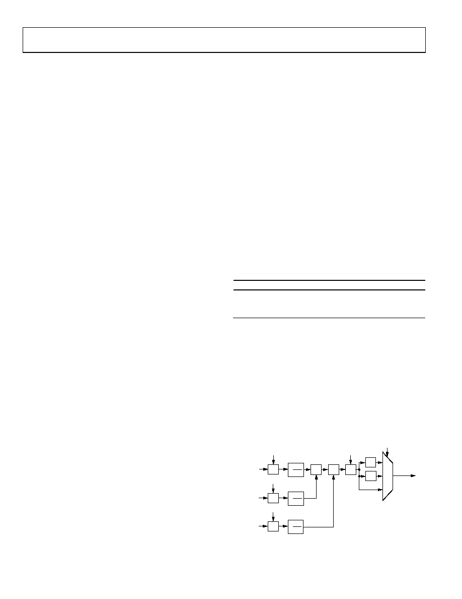
One of the three channels is represented in Figure 13. In each
processing channel the three inputs are multiplied by three
separate coefficients marked a1, a2, and a3. These coefficients
are divided by 4096 to obtain nominal values ranging from
–0.9998 to +0.9998. The variable labeled a4 is used as an offset
control. The CSC_mode setting is the same for all three
processing channels. This multiplies all coefficients and offsets
by a factor of 2csc_mode.
The functional diagram for a single channel of the CSC as
shown in Figure 13 is repeated for the remaining G and B
channels. The coefficients for these channels are b1, b2, b3, b4,
c1, c2, c3, and c4.
05087-
013
×2
2
1
0
×
a1[12:0]
a2[12:0]
a3[12:0]
RIN [11:0]
BIN [11:0]
GIN [11:0]
+
×4
CSC_MODE[1:0]
a4[12:0]
ROUT [11:0]
+
1
4096
×
1
4096
×
1
4096
×
+
Figure 13. Single CSC Channel
相关PDF资料 |
PDF描述 |
|---|---|
| S01-02-R | SOLDER SLEEVE IMMERS RESIS .650" |
| ILSB1206ER180K | INDUCTOR 18UH 10% 1206 |
| 242489-000 | CWT-3811 |
| VI-J10-EX | CONVERTER MOD DC/DC 5V 75W |
| GEC20DRYH-S734 | CONN EDGECARD 40POS DIP .100 SLD |
相关代理商/技术参数 |
参数描述 |
|---|---|
| AD9880XSTZ-100 | 制造商:Analog Devices 功能描述:IC, ANALOG/HDMI DUAL DISPLAY INTERFACE, PQFP100 |
| AD9882 | 制造商:AD 制造商全称:Analog Devices 功能描述:Dual Interface for Flat Panel Displays |
| AD9882/PCB | 制造商:Analog Devices 功能描述:DUAL INTRFC FOR FLAT PNL DISPLAY 100LQFP - Bulk |
| AD9882A | 制造商:AD 制造商全称:Analog Devices 功能描述:Dual Interface for Flat Panel Displays |
| AD9882A/PCB | 制造商:AD 制造商全称:Analog Devices 功能描述:Dual Interface for Flat Panel Displays |
发布紧急采购,3分钟左右您将得到回复。