- 您现在的位置:买卖IC网 > PDF目录1894 > AD9957BSVZ-REEL (Analog Devices Inc)IC DDS 1GSPS 14BIT IQ 100TQFP PDF资料下载
参数资料
| 型号: | AD9957BSVZ-REEL |
| 厂商: | Analog Devices Inc |
| 文件页数: | 16/64页 |
| 文件大小: | 0K |
| 描述: | IC DDS 1GSPS 14BIT IQ 100TQFP |
| 产品培训模块: | Direct Digital Synthesis Tutorial Series (1 of 7): Introduction Direct Digital Synthesizer Tutorial Series (7 of 7): DDS in Action Direct Digital Synthesis Tutorial Series (3 of 7): Angle to Amplitude Converter Direct Digital Synthesis Tutorial Series (6 of 7): SINC Envelope Correction Direct Digital Synthesis Tutorial Series (4 of 7): Digital-to-Analog Converter Direct Digital Synthesis Tutorial Series (2 of 7): The Accumulator |
| 标准包装: | 1,000 |
| 分辨率(位): | 14 b |
| 主 fclk: | 1GHz |
| 调节字宽(位): | 32 b |
| 电源电压: | 1.8V, 3.3V |
| 工作温度: | -40°C ~ 85°C |
| 安装类型: | 表面贴装 |
| 封装/外壳: | 100-TQFP 裸露焊盘 |
| 供应商设备封装: | 100-TQFP-EP(14x14) |
| 包装: | 带卷 (TR) |
| 配用: | AD9957/PCBZ-ND - BOARD EVAL AD9957 QUADRATURE MOD |
第1页第2页第3页第4页第5页第6页第7页第8页第9页第10页第11页第12页第13页第14页第15页当前第16页第17页第18页第19页第20页第21页第22页第23页第24页第25页第26页第27页第28页第29页第30页第31页第32页第33页第34页第35页第36页第37页第38页第39页第40页第41页第42页第43页第44页第45页第46页第47页第48页第49页第50页第51页第52页第53页第54页第55页第56页第57页第58页第59页第60页第61页第62页第63页第64页
Data Sheet
AD9957
Rev. C | Page 23 of 64
Encoding and pulse shaping of symbols must be implemented
before the data is presented to the input of the AD9957. Data
delivered to the input of the AD9957 may be formatted as either
twos complement or offset binary (see the Data Format bit in
Table 13). In BFI mode, the bit sequence order can be set to
either MSB-first or LSB-first (via the Blackfin Bit Order bit).
INVERSE CCI FILTER
The inverse cascaded comb integrator (CCI) filter predistorts
the data, compensating for the slight attenuation gradient imposed
by the CCI filter (see the Programmable Interpolating Filter
section). Data entering the first half-band filter occupies a maxi-
mum bandwidth of fIQ as defined by Nyquist (where fIQ is the
sample rate at the input of the first half-band filter); see Figure 33.
If the CCI filter is used, the inband attenuation gradient can pose a
problem for applications requiring an extremely flat pass band.
For example, if the spectrum of the data supplied to the AD9957
occupies a significant portion of the fDATA region, the higher
frequencies of the data spectrum are slightly more attenuated
than the lower frequencies (the worst-case overall droop from
f = 0 to fDATA is <0.8 dB). The inverse CCI filter has a response
characteristic that is the inverse of the CCI filter response over
the fIQ region.
INBAND
ATTENUATION
GRADIENT
CCI FILTER RESPONSE
fIQ
4
fIQ
f
06384-
013
Figure 33. CCI Filter Response
The product of the two responses yields an extremely flat
pass band (±0.05 dB over the baseband Nyquist bandwidth)
eliminating the inband attenuation gradient introduced by the
CCI filter. The cost is a slight attenuation of the input signal
(approximately 0.5 dB for a CCI interpolation rate of 2, and
0.8 dB for higher interpolation rates).
The inverse CCI filter can be bypassed using the appropriate bit
in the register map; it is automatically bypassed if the CCI inter-
polation rate is 1×. When bypassed, power to the stage turns off
to reduce power consumption.
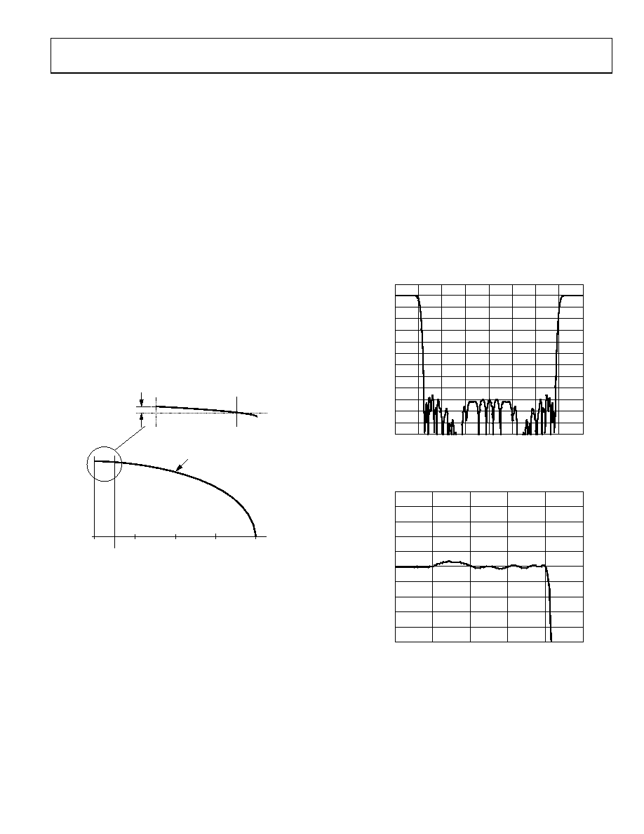
FIXED INTERPOLATOR (4×)
This block is a fixed 4× rate interpolator, implemented as a
cascade of two half-band filters. Together, the sampling rate
of these two filters increases by a factor of four while preserving
the spectrum of the baseband signal applied at the input. Both
are linear phase filters; virtually no phase distortion is intro-
duced within their pass bands. Their combined insertion loss
is 0.01 dB, preserving the relative amplitude of the input signal.
The filters are designed to deliver a composite performance that
yields a usable pass band of 40% of the input sample rate. Within
that pass band, ripple does not exceed 0.002 dB peak-to-peak.
The stop band extends from 60% to 340% of the input sample
rate and offers a minimum of 85 dB attenuation. Figure 34 and
Figure 35 show the composite response of the two half-band filters.
–120
–110
–100
–90
–80
–70
–60
–50
–40
–30
–20
–10
0
10
0
0.5
1.0
1.5
2.0
2.5
3.0
3.5
4.0
06384-
014
(d
B)
fI
Figure 34. Half-Band 1 and Half-Band 2 Composite Response
(Frequency Scaled to Input Sample Rate of Half-Band 1)
–0.010
–0.008
0.008
–0.006
0.006
–0.004
0.004
–0.002
0.002
0
0.010
0
0.1
0.2
0.3
0.4
0.5
06384-
015
(d
B)
fI
Figure 35. Composite Pass-Band Detail
(Frequency Scaled to Input Sample Rate of Half-Band 1)
In BFI mode, there are two additional half-band filters resident,
yielding a total fixed interpolation factor of 16×. The extra BFI
filters use the same filter tap coefficient values as the QDUC
half-band filters, but their data pathway is 16 bits (instead of
18 bits as with the QDUC half-band filters). As such, baseband
quantization noise is higher in BFI mode.
相关PDF资料 |
PDF描述 |
|---|---|
| AD9958BCPZ-REEL7 | IC DDS DUAL 10BIT DAC 56LFCSP |
| AD9959BCPZ-REEL7 | IC DDS QUAD 10BIT DAC 56LFCSP |
| AD9970BCPZRL7 | IC PROCESSOR CCD SIGNAL 32-LFCSP |
| AD9972BBCZRL | IC CCD SGNL PROC 14BIT 100CSPBGA |
| AD9973BBCZ | IC CCD SGNL PROC 14BIT 84-CSPBGA |
相关代理商/技术参数 |
参数描述 |
|---|---|
| AD9957BSVZREEL13 | 制造商:AD 制造商全称:Analog Devices 功能描述:1 GSPS Quadrature Digital Upconverter w/18-Bit IQ Data Path and 14-Bit DAC |
| AD9958 | 制造商:AD 制造商全称:Analog Devices 功能描述:2-Channel 500 MSPS DDS with 10-Bit DACs |
| AD9958 PCB | 制造商:Analog Devices 功能描述:EVAL BOARD ((NS)) |
| AD9958/PCB | 制造商:Analog Devices 功能描述:Evaluation Board For 2-Channel 500 MSPS DDS With 10-Bit DACs 制造商:Rochester Electronics LLC 功能描述:- Bulk 制造商:Analog Devices 功能描述:IC 10-BIT DAC DDS |
| AD9958/PCBZ | 功能描述:BOARD EVALUATION FOR AD9958 RoHS:是 类别:编程器,开发系统 >> 评估演示板和套件 系列:AgileRF™ 标准包装:1 系列:PSoC® 主要目的:电源管理,热管理 嵌入式:- 已用 IC / 零件:- 主要属性:- 次要属性:- 已供物品:板,CD,电源 |
发布紧急采购,3分钟左右您将得到回复。