- 您现在的位置:买卖IC网 > PDF目录19376 > ADSP-21061KSZ-133 (Analog Devices Inc)IC DSP CONTROLLER 32BIT 240MQFP PDF资料下载
参数资料
| 型号: | ADSP-21061KSZ-133 |
| 厂商: | Analog Devices Inc |
| 文件页数: | 4/52页 |
| 文件大小: | 0K |
| 描述: | IC DSP CONTROLLER 32BIT 240MQFP |
| 产品培训模块: | SHARC Processor Overview |
| 标准包装: | 1 |
| 系列: | SHARC® |
| 类型: | 浮点 |
| 接口: | 同步串行端口(SSP) |
| 时钟速率: | 33MHz |
| 非易失内存: | 外部 |
| 芯片上RAM: | 128kB |
| 电压 - 输入/输出: | 5.00V |
| 电压 - 核心: | 5.00V |
| 工作温度: | 0°C ~ 85°C |
| 安装类型: | 表面贴装 |
| 封装/外壳: | 240-BFQFP 裸露焊盘 |
| 供应商设备封装: | 240-MQFP-EP(32x32) |
| 包装: | 托盘 |
第1页第2页第3页当前第4页第5页第6页第7页第8页第9页第10页第11页第12页第13页第14页第15页第16页第17页第18页第19页第20页第21页第22页第23页第24页第25页第26页第27页第28页第29页第30页第31页第32页第33页第34页第35页第36页第37页第38页第39页第40页第41页第42页第43页第44页第45页第46页第47页第48页第49页第50页第51页第52页
Rev. D | Page 12 of 52 | May 2013
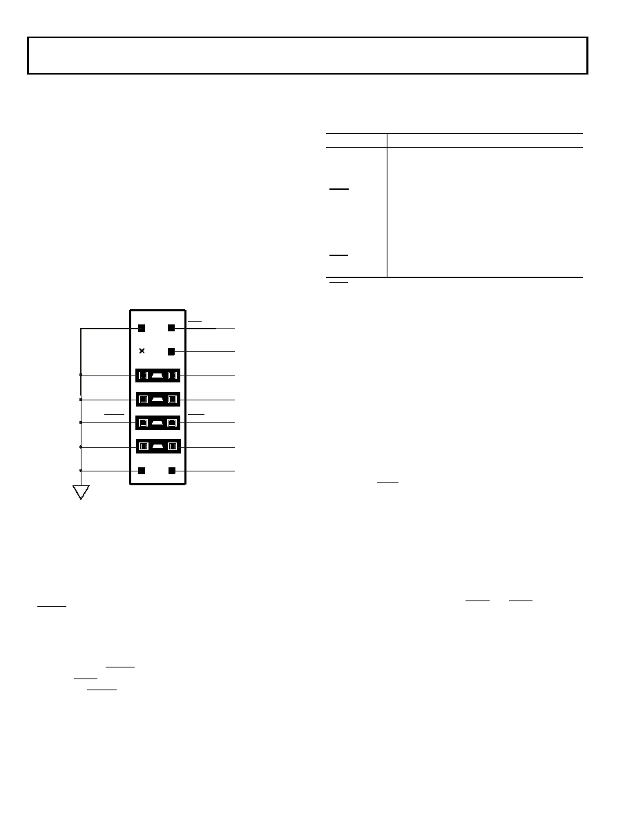
TARGET BOARD CONNECTOR FOR EZ-ICE PROBE
The ADSP-2106x EZ-ICE Emulator uses the IEEE 1149.1 JTAG
test access port of the ADSP-2106x to monitor and control the
target board processor during emulation. The EZ-ICE probe
requires the ADSP-2106x’s CLKIN, TMS, TCK, TDI, TDO, and
GND signals be made accessible on the target system via a
14-pin connector (a 2-row, 7-pin strip header) such as that
shown in Figure 5. The EZ-ICE probe plugs directly onto this
connector for chip-on-board emulation. You must add this con-
nector to your target board design if you intend to use the
ADSP-2106x EZ-ICE. The total trace length between the EZ-
ICE connector and the farthest device sharing the EZ-ICE JTAG
pin should be limited to 15 inches maximum for guaranteed
operation. This length restriction must include EZ-ICE JTAG
signals that are routed to one or more ADSP-2106x devices, or a
combination of ADSP-2106x devices and other JTAG devices
on the chain.
The 14-pin, 2-row pin strip header is keyed at the Pin 3 loca-
tion—Pin 3 must be removed from the header. The pins must be
0.025 inch square and at least 0.20 inches in length. Pin spacing
should be 0.1 0.1 inches. Pin strip headers are available from
vendors such as 3M, McKenzie, and Samtec. The BTMS, BTCK,
BTRST, and BTDI signals are provided so that the test access
port can also be used for board-level testing.
When the connector is not being used for emulation, place
jumpers between the Bxxx pins and the xxx pins as shown in
Figure 5. If you are not going to use the test access port for
board testing, tie BTRST to GND and tie or pull up BTCK to
VDD. The TRST pin must be asserted (pulsed low) after power-
up (through BTRST on the connector) or held low for proper
operation of the ADSP-2106x. None of the Bxxx pins (Pins 5, 7,
9, and 11) are connected on the EZ-ICE probe.
The JTAG signals are terminated on the EZ-ICE probe as shown
in Table 3.
Figure 6 shows JTAG scan path connections for systems that
contain multiple ADSP-2106x processors.
Connecting CLKIN to Pin 4 of the EZ-ICE header is optional.
The emulator only uses CLKIN when directed to perform oper-
ations such as starting, stopping, and single-stepping multiple
ADSP-2106xs in a synchronous manner. If you do not need
these operations to occur synchronously on the multiple proces-
sors, simply tie Pin 4 of the EZ-ICE header to ground.
If synchronous multiprocessor operations are needed and
CLKIN is connected, clock skew between the multiple
ADSP-21061 processors and the CLKIN pin on the EZ-ICE
header must be minimal. If the skew is too large, synchronous
operations may be off by one or more cycles between proces-
sors. For synchronous multiprocessor operation TCK, TMS,
CLKIN, and EMU should be treated as critical signals in terms
of skew, and should be laid out as short as possible on your
board. If TCK, TMS, and CLKIN are driving a large number of
ADSP-21061s (more than eight) in your system, then treat them
as a “clock tree” using multiple drivers to minimize skew. (See
Figure 7 below and “JTAG Clock Tree” and “Clock Distribu-
tion” in the “High Frequency Design Considerations” section of
the ADSP-2106x SHARC User’s Manual.)
If synchronous multiprocessor operations are not needed (i.e.,
CLKIN is not connected), just use appropriate parallel termina-
tion on TCK and TMS. TDI, TDO, EMU, and TRST are not
critical signals in terms of skew.
Figure 5. Target Board Connector For ADSP-2106x EZ-ICE Emulator
(Jumpers in Place)
TOP VIEW
13
14
11
12
910
9
7
8
56
3
4
12
EMU
GND
TMS
TCK
TRST
TDI
TDO
GND
KEY (NO PIN)
BTMS
BTCK
BTRST
BTDI
GND
Table 3. Core Instruction Rate/CLKIN Ratio Selection
Signal
Termination
TMS
Driven Through 22 Resistor (16 mA Driver)
TCK
Driven at 10 MHz Through 22 Resistor (16 mA
Driver)
TRST1
1 TRST is driven low until the EZ-ICE probe is turned on by the emulator at software
startup. After software startup, is driven high.
Active Low Driven Through 22 Resistor (16 mA
Driver) (Pulled Up by On-Chip 20 k Resistor)
TDI
Driven by 22 Resistor (16 mA Driver)
TDO
One TTL Load, Split Termination (160/220)
CLKIN
One TTL Load, Split Termination (160/220)
EMU
Active Low, 4.7 k Pull-Up Resistor, One TTL Load
(Open-Drain Output from the DSP)
相关PDF资料 |
PDF描述 |
|---|---|
| VI-B31-CY-F2 | CONVERTER MOD DC/DC 12V 50W |
| TAJY156M025RNJ | CAP TANT 15UF 25V 20% 2917 |
| 5717-RC | CHOKE RF HI CURR 500UH 15% RAD |
| VI-B30-CY-F2 | CONVERTER MOD DC/DC 5V 50W |
| MAX6665ASA70+T | IC FAN CNTRL/DRVR 8-SOIC |
相关代理商/技术参数 |
参数描述 |
|---|---|
| ADSP-21061KSZ-160 | 功能描述:IC DSP CONTROLLER 1MBIT 240MQFP RoHS:是 类别:集成电路 (IC) >> 嵌入式 - DSP(数字式信号处理器) 系列:SHARC® 标准包装:40 系列:TMS320DM64x, DaVinci™ 类型:定点 接口:I²C,McASP,McBSP 时钟速率:400MHz 非易失内存:外部 芯片上RAM:160kB 电压 - 输入/输出:3.30V 电压 - 核心:1.20V 工作温度:0°C ~ 90°C 安装类型:表面贴装 封装/外壳:548-BBGA,FCBGA 供应商设备封装:548-FCBGA(27x27) 包装:托盘 配用:TMDSDMK642-0E-ND - DEVELPER KIT W/NTSC CAMERA296-23038-ND - DSP STARTER KIT FOR TMS320C6416296-23059-ND - FLASHBURN PORTING KIT296-23058-ND - EVAL MODULE FOR DM642TMDSDMK642-ND - DEVELOPER KIT W/NTSC CAMERA |
| ADSP-21061KSZ-200 | 功能描述:IC DSP CONTROLLER 32BIT 240MQFP RoHS:是 类别:集成电路 (IC) >> 嵌入式 - DSP(数字式信号处理器) 系列:SHARC® 标准包装:40 系列:TMS320DM64x, DaVinci™ 类型:定点 接口:I²C,McASP,McBSP 时钟速率:400MHz 非易失内存:外部 芯片上RAM:160kB 电压 - 输入/输出:3.30V 电压 - 核心:1.20V 工作温度:0°C ~ 90°C 安装类型:表面贴装 封装/外壳:548-BBGA,FCBGA 供应商设备封装:548-FCBGA(27x27) 包装:托盘 配用:TMDSDMK642-0E-ND - DEVELPER KIT W/NTSC CAMERA296-23038-ND - DSP STARTER KIT FOR TMS320C6416296-23059-ND - FLASHBURN PORTING KIT296-23058-ND - EVAL MODULE FOR DM642TMDSDMK642-ND - DEVELOPER KIT W/NTSC CAMERA |
| ADSP-21061L | 制造商:Analog Devices 功能描述: |
| ADSP-21061LAS-160 | 制造商:AD 制造商全称:Analog Devices 功能描述:ADSP-2106x SHARC DSP Microcomputer Family |
| ADSP-21061LAS-176 | 制造商:Analog Devices 功能描述:DSP Floating-Point 32-Bit 44MHz 44MIPS 240-Pin MQFP Tray 制造商:Analog Devices 功能描述:IC MICROCOMPUTER DSP |
发布紧急采购,3分钟左右您将得到回复。