- 您现在的位置:买卖IC网 > PDF目录16699 > AFE7222EVM (Texas Instruments)EVAL MODULE FOR AFE7222 PDF资料下载
参数资料
| 型号: | AFE7222EVM |
| 厂商: | Texas Instruments |
| 文件页数: | 80/106页 |
| 文件大小: | 0K |
| 描述: | EVAL MODULE FOR AFE7222 |
| 标准包装: | 1 |
| 主要目的: | 接口,模拟前端(AFE) |
| 嵌入式: | 否 |
| 已用 IC / 零件: | AFE7222 |
| 已供物品: | 板 |
| 其它名称: | 296-30300 AFE7222EVM-ND |
第1页第2页第3页第4页第5页第6页第7页第8页第9页第10页第11页第12页第13页第14页第15页第16页第17页第18页第19页第20页第21页第22页第23页第24页第25页第26页第27页第28页第29页第30页第31页第32页第33页第34页第35页第36页第37页第38页第39页第40页第41页第42页第43页第44页第45页第46页第47页第48页第49页第50页第51页第52页第53页第54页第55页第56页第57页第58页第59页第60页第61页第62页第63页第64页第65页第66页第67页第68页第69页第70页第71页第72页第73页第74页第75页第76页第77页第78页第79页当前第80页第81页第82页第83页第84页第85页第86页第87页第88页第89页第90页第91页第92页第93页第94页第95页第96页第97页第98页第99页第100页第101页第102页第103页第104页第105页第106页
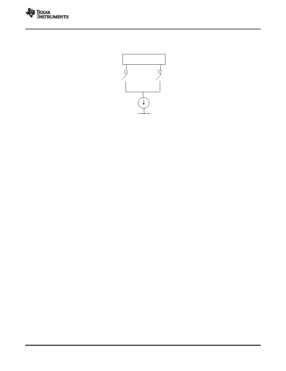
IDAC
IOUTP_A_DAC
IOUTN_A_DAC
External Termination
I
= 16 * (VREF/RBIAS), where VREF = 1.2 V
OUTFS
SLOS711B – NOVEMBER 2011 – REVISED MARCH 2012
IOUTFS = 16 × (VREF/RBIAS), where VREF = 1.2V.
Figure 9-8. Current Steering Architecture of DAC
9.10 FIFO
The 8-Deep FIFO is used to handoff the data from the digital clock (DAC_DCLKIN) domain to the
DAC_CLK domain (or the divided version of DAC_CLK if interpolation is used). The FIFO has a read and
write pointer, which are initialized to 4 away from each other when the chip is either reset or synchronized.
The write pointer increments with DAC_DCLKIN whereas the read pointer increments with DAC_DCLKIN
(or the divided version). Ideally, the read and write pointers maintain the difference of 4. However, if there
is a drift in the relative phases of the two clocks, the instantaneous values of the read and write pointers
can differ from 4. If the pointers come to within 2 positions of each other, the FIFO can be set to identify
that condition as a possible "collision" condition and can shut off the DAC outputs by pulling it to mid code.
A stoppage of the input clock can also be detected by the FIFO.
9.11 TRANSMIT INTERPOLATION FILTERS
The AFE7225/7222 can enable 2x or 4x interpolation using on-chip half-band interpolation filters. The
additional oversampling provided by interpolation can be used to reduce the order of the low pass anti-
aliasing filter that follows the transmit DACs or so that the digital carrier can be block shifted by the coarse
mixer to a higher output IF.
While interpolating by a factor of 2, the DAC_DCLKIN rate should be set to half of the input clock rate.
While interpolating by a factor of 4, the DAC_DCLKIN rate should be set to one fourth of the input clock
rate.
Each channel has two filters TxFIR1, and TxFIR2, of which TxFIR1 alone is enabled in the Interpolate by
2 mode, Both filters are enabled in Intertpolate by 4 mode. The 2 filters in each of the two channels can
individually be configured to operate in the ‘low pass ‘ or the high pass mode. By default, all filters are
configured to opearate in the low pass mode. The following table lists the address and data mask values
to be programmed to configure each of these filters in the high pass mode.
TXFIR1 is a 43 tap half-band filter. The transition band is from 0.4 to 0.6 of FCLKFIR1/2, and the stop band
attenuation is 70 dB. Pass band ripple is less than 0.1dB. It has the following coefficients (listed only up to
the middle one)
TXFIR1 (interpolation filter 1)
coefficients = [12 0 –33 0 73 0 –143 0 254 0 –426 0 685 0 –1090 0 1781 0 –3286 0 10365 16384 ]
The frequency response is shown below.
Copyright 2011–2012, Texas Instruments Incorporated
APPLICATION INFORMATION
75
相关PDF资料 |
PDF描述 |
|---|---|
| ECE-V1EA100NP | CAP ALUM 10UF 25V 20% SMD |
| 0210491116 | CABLE JUMPER 1.25MM .305M 39POS |
| UPM1J270MED1TD | CAP ALUM 27UF 63V 20% RADIAL |
| RNF-100-1-1/4-RD-SP | HEAT SHRINK TUBING |
| RNF-100-1-1/4-BU-SP | HEAT SHRINK TUBING |
相关代理商/技术参数 |
参数描述 |
|---|---|
| AFE7222IRGC25 | 功能描述:射频前端 Dual 12B,65MSPS ADC RoHS:否 制造商:Skyworks Solutions, Inc. 类型: 工作频率:2.4 GHz, 5 GHz 最大数据速率:54 Mbps 噪声系数: 工作电源电压:3.3 V 电源电流:180 mA 最大工作温度:+ 85 C 安装风格:SMD/SMT 封装 / 箱体:QFN-32 |
| AFE7222IRGCR | 功能描述:射频前端 Dual 12B,65MSPS ADC RoHS:否 制造商:Skyworks Solutions, Inc. 类型: 工作频率:2.4 GHz, 5 GHz 最大数据速率:54 Mbps 噪声系数: 工作电源电压:3.3 V 电源电流:180 mA 最大工作温度:+ 85 C 安装风格:SMD/SMT 封装 / 箱体:QFN-32 |
| AFE7222IRGCT | 功能描述:射频前端 Dual 12B,65MSPS ADC RoHS:否 制造商:Skyworks Solutions, Inc. 类型: 工作频率:2.4 GHz, 5 GHz 最大数据速率:54 Mbps 噪声系数: 工作电源电压:3.3 V 电源电流:180 mA 最大工作温度:+ 85 C 安装风格:SMD/SMT 封装 / 箱体:QFN-32 |
| AFE7225 | 制造商:TI 制造商全称:Texas Instruments 功能描述:Analog Front End Wideband Mixed-Signal Transceiver |
| AFE7225EVM | 功能描述:射频开发工具 AFE7225 Eval Mod RoHS:否 制造商:Taiyo Yuden 产品:Wireless Modules 类型:Wireless Audio 工具用于评估:WYSAAVDX7 频率: 工作电源电压:3.4 V to 5.5 V |
发布紧急采购,3分钟左右您将得到回复。