- 您现在的位置:买卖IC网 > PDF目录12024 > AT89C51ID2-SLSUM (Atmel)IC 8051 MCU FLASH 64K 44PLCC PDF资料下载
参数资料
| 型号: | AT89C51ID2-SLSUM |
| 厂商: | Atmel |
| 文件页数: | 129/157页 |
| 文件大小: | 0K |
| 描述: | IC 8051 MCU FLASH 64K 44PLCC |
| 产品培训模块: | MCU Product Line Introduction |
| 标准包装: | 972 |
| 系列: | 89C |
| 核心处理器: | 8051 |
| 芯体尺寸: | 8-位 |
| 速度: | 60MHz |
| 连通性: | I²C,SPI,UART/USART |
| 外围设备: | POR,PWM,WDT |
| 输入/输出数: | 34 |
| 程序存储器容量: | 64KB(64K x 8) |
| 程序存储器类型: | 闪存 |
| EEPROM 大小: | 2K x 8 |
| RAM 容量: | 2K x 8 |
| 电压 - 电源 (Vcc/Vdd): | 2.7 V ~ 5.5 V |
| 振荡器型: | 外部 |
| 工作温度: | -40°C ~ 85°C |
| 封装/外壳: | 44-LCC(J 形引线) |
| 包装: | 管件 |
| 配用: | AT89OCD-01-ND - USB EMULATOR FOR AT8XC51 MCU |
第1页第2页第3页第4页第5页第6页第7页第8页第9页第10页第11页第12页第13页第14页第15页第16页第17页第18页第19页第20页第21页第22页第23页第24页第25页第26页第27页第28页第29页第30页第31页第32页第33页第34页第35页第36页第37页第38页第39页第40页第41页第42页第43页第44页第45页第46页第47页第48页第49页第50页第51页第52页第53页第54页第55页第56页第57页第58页第59页第60页第61页第62页第63页第64页第65页第66页第67页第68页第69页第70页第71页第72页第73页第74页第75页第76页第77页第78页第79页第80页第81页第82页第83页第84页第85页第86页第87页第88页第89页第90页第91页第92页第93页第94页第95页第96页第97页第98页第99页第100页第101页第102页第103页第104页第105页第106页第107页第108页第109页第110页第111页第112页第113页第114页第115页第116页第117页第118页第119页第120页第121页第122页第123页第124页第125页第126页第127页第128页当前第129页第130页第131页第132页第133页第134页第135页第136页第137页第138页第139页第140页第141页第142页第143页第144页第145页第146页第147页第148页第149页第150页第151页第152页第153页第154页第155页第156页第157页
73
AT89C51ID2
4289C–8051–11/05
and RAM contents are preserved. The status of the Port pins during Power-Down mode
is detailed in Table 57.
Note:
VCC may be reduced to as low as V
RET during Power-Down mode to further reduce
power dissipation. Take care, however, that VDD is not reduced until Power-Down mode
is invoked.
Entering Power-Down Mode
To enter Power-Down mode, set PD bit in PCON register. The AT89C51ID2 enters the
Power-Down mode upon execution of the instruction that sets PD bit. The instruction
that sets PD bit is the last instruction executed.
Exiting Power-Down Mode
Note:
If VCC was reduced during the Power-Down mode, do not exit Power-Down mode until
VCC is restored to the normal operating level.
There are two ways to exit the Power-Down mode:
1.
Generate an enabled external interrupt.
–
The AT89C51ID2 provides capability to exit from Power-Down using INT0#,
INT1#.
Hardware clears PD bit in PCON register which starts the oscillator and
restores the clocks to the CPU and peripherals. Using INTx# input,
execution resumes when the input is released (see Figure 26). Execution
resumes with the interrupt service routine. Upon completion of the interrupt
service routine, program execution resumes with the instruction immediately
following the instruction that activated Power-Down mode.
Note:
The external interrupt used to exit Power-Down mode must be configured as level sensi-
tive (INT0# and INT1#) and must be assigned the highest priority. In addition, the
duration of the interrupt must be long enough to allow the oscillator to stabilize. The exe-
cution will only resume when the interrupt is deasserted.
Note:
Exit from power-down by external interrupt does not affect the SFRs nor the internal RAM
content.
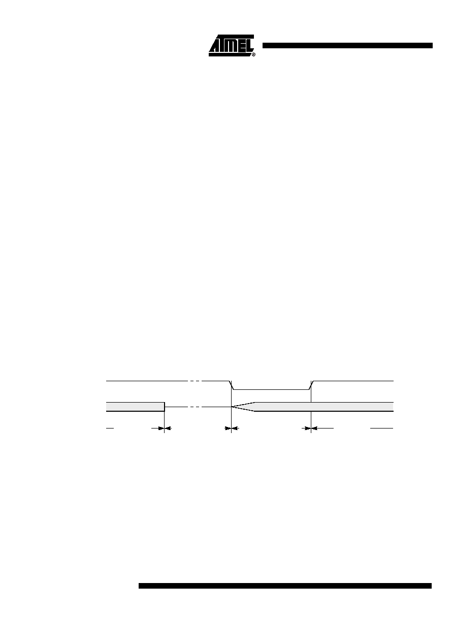
Figure 26. Power-Down Exit Waveform Using INT1:0#
2.
Generate a reset.
–
A logic high on the RST pin clears PD bit in PCON register directly and
asynchronously. This starts the oscillator and restores the clock to the CPU
and peripherals. Program execution momentarily resumes with the
instruction immediately following the instruction that activated Power-Down
mode and may continue for a number of clock cycles before the internal
reset algorithm takes control. Reset initializes the AT89C51ID2 and vectors
the CPU to address 0000h.
Note:
During the time that execution resumes, the internal RAM cannot be accessed; however,
it is possible for the Port pins to be accessed. To avoid unexpected outputs at the Port
INT1:0#
OSC
Power-down phase
Oscillator restart phase
Active phase
相关PDF资料 |
PDF描述 |
|---|---|
| AT91SAM7X128B-CU | IC MCU 128KB FLASH 100TFBGA |
| AT91SAM7XC128B-AU | MCU ARM 128K HS FLASH 100-LQFP |
| ATSAM3U1CA-CU | IC MCU 32BIT 64KB FLASH 100TFBGA |
| 1981584-1 | CONN RCPT MICRO USB TYPE AB |
| 1981568-1 | CONN RCPT MICRO USB B R/A SMD |
相关代理商/技术参数 |
参数描述 |
|---|---|
| AT89C51ID2-SMSIM | 制造商:ATMEL 制造商全称:ATMEL Corporation 功能描述:8-bit Flash Microcontroller |
| AT89C51ID2-UM | 制造商:ATMEL 制造商全称:ATMEL Corporation 功能描述:8-bit Flash Microcontroller |
| AT89C51RB2 | 制造商:ATMEL 制造商全称:ATMEL Corporation 功能描述:8-bit Microcontroller with 16K/ 32K Bytes Flash |
| AT89C51RB2/RC2 | 制造商:ATMEL 制造商全称:ATMEL Corporation 功能描述:AT89C51RB2/RC2 [Updated 4/03. 125 Pages] |
| AT89C51RB2_06 | 制造商:ATMEL 制造商全称:ATMEL Corporation 功能描述:8-bit Microcontroller with 16K/ 32K Bytes Flash |
发布紧急采购,3分钟左右您将得到回复。