参数资料
| 型号: | AT90LS2343-1SI |
| 厂商: | Atmel |
| 文件页数: | 51/63页 |
| 文件大小: | 0K |
| 描述: | IC MCU 2K FLASH 1MHZ IND 8-SOIC |
| 标准包装: | 95 |
| 系列: | AVR® 90LS |
| 核心处理器: | AVR |
| 芯体尺寸: | 8-位 |
| 速度: | 1MHz |
| 连通性: | SPI |
| 外围设备: | 欠压检测/复位,POR,WDT |
| 输入/输出数: | 5 |
| 程序存储器容量: | 2KB(1K x 16) |
| 程序存储器类型: | 闪存 |
| EEPROM 大小: | 128 x 8 |
| RAM 容量: | 128 x 8 |
| 电压 - 电源 (Vcc/Vdd): | 2.7 V ~ 6 V |
| 振荡器型: | 内部 |
| 工作温度: | -40°C ~ 85°C |
| 封装/外壳: | 8-SOIC(0.209",5.30mm 宽) |
| 包装: | 管件 |
第1页第2页第3页第4页第5页第6页第7页第8页第9页第10页第11页第12页第13页第14页第15页第16页第17页第18页第19页第20页第21页第22页第23页第24页第25页第26页第27页第28页第29页第30页第31页第32页第33页第34页第35页第36页第37页第38页第39页第40页第41页第42页第43页第44页第45页第46页第47页第48页第49页第50页当前第51页第52页第53页第54页第55页第56页第57页第58页第59页第60页第61页第62页第63页
PIC16C433
DS41139B-page 54
Preliminary
2002 Microchip Technology Inc.
9.2.5
INTERNAL 4 MHz RC OSCILLATOR
The internal RC oscillator provides a fixed 4 MHz (nom-
inal) system clock at VDD = 5V and 25°C. See
Section 13.0 for information on variation over voltage
and temperature.
In addition, a calibration instruction is programmed into
the last address of the program memory, which con-
tains the calibration value for the internal RC oscillator.
This value is programmed as a RETLW XX instruction,
where XX is the calibration value. In order to retrieve
the calibration value, issue a CALL
YY
instruction,
where YY is the last location in program memory. Con-
trol will be returned to the user’s program with the cali-
bration value loaded into the W register. The program
should then perform a MOVWF OSCCAL instruction to
load the value into the internal RC oscillator trim
register.
OSCCAL, when written to with the calibration value, will
“trim” the internal oscillator to remove process variation
from the oscillator frequency. Bits <7:4>, CAL<3:0> are
used for fine calibration, while bit3, CALFST, and bit2,
CALSLW, are used for more coarse adjustment.
Adjusting CAL<3:0> from 0000 to 1111 yields a higher
clock speed. Set CALFST = 1 for greater increase in
frequency, or set CALSLW = 1 for greater decrease in
frequency. Note that bits 1 and 0 of OSCCAL are unim-
plemented and should be written as 0, when modifying
OSCCAL for compatibility with future devices.
9.2.6
CLKOUT
The PIC16C433 can be configured to provide a clock
out signal (CLKOUT) on pin 3, when the configuration
word address (2007h) is programmed with FOSC2,
FOSC1, and FOSC0, equal to 101 for INTRC or 111 for
EXTRC. The oscillator frequency, divided by 4, can be
used for test purposes or to synchronize other logic.
9.3
RESET
The PIC16C433 differentiates between various kinds of
RESET:
Power-on Reset (POR)
MCLR Reset during normal operation
MCLR Reset during SLEEP
WDT Reset (normal operation)
Some registers are not affected in any RESET condi-
tion; their status is unknown on POR and unchanged in
any other RESET. Most other registers are reset to a
“RESET state” on Power-on Reset (POR), MCLR
Reset, WDT Reset, and MCLR Reset during SLEEP.
They are not affected by a WDT wake-up, which is
viewed as the resumption of normal operation. The TO
and PD bits are set or cleared differently in different
RESET situations, as indicated in Table 9-5. These bits
are used in software to determine the nature of the
RESET. See Table 9-6 for a full description of RESET
states of all registers.
A simplified block diagram of the On-Chip Reset circuit
is shown in Figure 9-6.
The PIC16C433 has a MCLR noise filter in the MCLR
Reset path. The filter will detect and ignore small
pulses.
It should be noted that a WDT Reset does not drive
MCLR pin low.
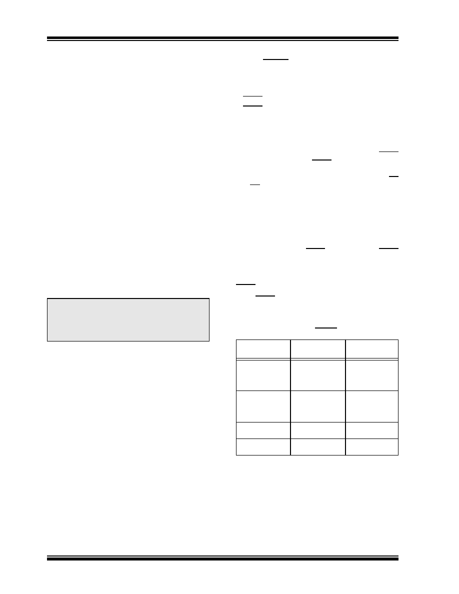
When MCLR is asserted, the state of the OSC1/CLKIN
and CLKOUT/OSC2 pins are as follows:
Note:
Please note that erasing the device will
also erase the pre-programmed internal
calibration value for the internal oscillator.
The calibration value must be saved prior
to erasing the part.
TABLE 9-3:
CLKIN/CLKOUT PIN STATES
WHEN MCLR ASSERTED
Oscillator Mode
OSC1/CLKIN Pin
OSC2/CLKOUT
Pin
EXTRC, CLKOUT
on OSC2
OSC1 pin is
tri-stated and
driven by external
circuit
OSC2 pin is
driven low
EXTRC, OSC2
is I/O
OSC1 pin is
tri-stated and
driven by external
circuit
OSC2 pin is
tri-state input
INTRC, CLKOUT
on OSC2
OSC1 pin is
tri-state input
OSC2 pin is
driven low
INTRC, OSC2
is I/O
OSC1 pin is
tri-state input
OSC2 pin is
tri-state input
相关PDF资料 |
PDF描述 |
|---|---|
| AT90PWM1-16MUR | MCU AVR 8K ISP FLASH 16MHZ 32QFN |
| AT90S1200A-4SC | MCU 1K FLASH 4MHZ LV 20-SOIC |
| AT90S2313-10PC | IC MCU 2K FLSH 10MHZ UART 20DIP |
| AT90S4433-8AC | IC MCU 4K FLSH 8MHZ A/D 32TQFP |
| AT90S8515A-8PC | IC MCU 8K FLSH 8MHZ 40DIP |
相关代理商/技术参数 |
参数描述 |
|---|---|
| AT90LS2343-4PC | 功能描述:8位微控制器 -MCU 2k bit RoHS:否 制造商:Silicon Labs 核心:8051 处理器系列:C8051F39x 数据总线宽度:8 bit 最大时钟频率:50 MHz 程序存储器大小:16 KB 数据 RAM 大小:1 KB 片上 ADC:Yes 工作电源电压:1.8 V to 3.6 V 工作温度范围:- 40 C to + 105 C 封装 / 箱体:QFN-20 安装风格:SMD/SMT |
| AT90LS2343-4PI | 功能描述:8位微控制器 -MCU 2k bit RoHS:否 制造商:Silicon Labs 核心:8051 处理器系列:C8051F39x 数据总线宽度:8 bit 最大时钟频率:50 MHz 程序存储器大小:16 KB 数据 RAM 大小:1 KB 片上 ADC:Yes 工作电源电压:1.8 V to 3.6 V 工作温度范围:- 40 C to + 105 C 封装 / 箱体:QFN-20 安装风格:SMD/SMT |
| AT90LS2343-4SC | 制造商:ATMEL 制造商全称:ATMEL Corporation 功能描述:8-Bit Microcontroller with 2K Bytes of In-System Programmable Flash |
| AT90LS2343-4SI | 功能描述:8位微控制器 -MCU 2k bit RoHS:否 制造商:Silicon Labs 核心:8051 处理器系列:C8051F39x 数据总线宽度:8 bit 最大时钟频率:50 MHz 程序存储器大小:16 KB 数据 RAM 大小:1 KB 片上 ADC:Yes 工作电源电压:1.8 V to 3.6 V 工作温度范围:- 40 C to + 105 C 封装 / 箱体:QFN-20 安装风格:SMD/SMT |
| AT90LS2343-4SI SL383 | 制造商:Atmel Corporation 功能描述:4MHZSOICIND TEMP3.0V |
发布紧急采购,3分钟左右您将得到回复。