- 您现在的位置:买卖IC网 > PDF目录12052 > ATMEGA164A-PU (Atmel)IC MCU AVR 16K 20MHZ 40PDIP PDF资料下载
参数资料
| 型号: | ATMEGA164A-PU |
| 厂商: | Atmel |
| 文件页数: | 123/160页 |
| 文件大小: | 0K |
| 描述: | IC MCU AVR 16K 20MHZ 40PDIP |
| 产品培训模块: | MCU Product Line Introduction megaAVR Introduction |
| 标准包装: | 14 |
| 系列: | AVR® ATmega |
| 核心处理器: | AVR |
| 芯体尺寸: | 8-位 |
| 速度: | 20MHz |
| 连通性: | I²C,SPI,UART/USART |
| 外围设备: | 欠压检测/复位,POR,PWM,WDT |
| 输入/输出数: | 32 |
| 程序存储器容量: | 16KB(8K x 16) |
| 程序存储器类型: | 闪存 |
| EEPROM 大小: | 512 x 8 |
| RAM 容量: | 1K x 8 |
| 电压 - 电源 (Vcc/Vdd): | 1.8 V ~ 5.5 V |
| 数据转换器: | A/D 8x10b |
| 振荡器型: | 内部 |
| 工作温度: | -40°C ~ 85°C |
| 封装/外壳: | 40-DIP(0.600",15.24mm) |
| 包装: | 管件 |
| 配用: | ATSTK600-RC05-ND - STK600 ROUTING CARD AVR |
第1页第2页第3页第4页第5页第6页第7页第8页第9页第10页第11页第12页第13页第14页第15页第16页第17页第18页第19页第20页第21页第22页第23页第24页第25页第26页第27页第28页第29页第30页第31页第32页第33页第34页第35页第36页第37页第38页第39页第40页第41页第42页第43页第44页第45页第46页第47页第48页第49页第50页第51页第52页第53页第54页第55页第56页第57页第58页第59页第60页第61页第62页第63页第64页第65页第66页第67页第68页第69页第70页第71页第72页第73页第74页第75页第76页第77页第78页第79页第80页第81页第82页第83页第84页第85页第86页第87页第88页第89页第90页第91页第92页第93页第94页第95页第96页第97页第98页第99页第100页第101页第102页第103页第104页第105页第106页第107页第108页第109页第110页第111页第112页第113页第114页第115页第116页第117页第118页第119页第120页第121页第122页当前第123页第124页第125页第126页第127页第128页第129页第130页第131页第132页第133页第134页第135页第136页第137页第138页第139页第140页第141页第142页第143页第144页第145页第146页第147页第148页第149页第150页第151页第152页第153页第154页第155页第156页第157页第158页第159页第160页
65
8272E–AVR–04/2013
ATmega164A/PA/324A/PA/644A/PA/1284/P
...
;
0x1F036
jmp
SPM_RDY
; SPM Ready Handler
;
0x1F03E
RESET: ldi
r16,high(RAMEND); Main program start
0x1F03F
out
SPH,r16
; Set Stack Pointer to top of RAM
0x1F040
ldi
r16,low(RAMEND)
0x1F041
out
SPL,r16
0x1F042
sei
; Enable interrupts
0x1FO43
<instr>
xxx
12.2.1
Moving Interrupts Between Application and Boot Space
The General Interrupt Control Register controls the placement of the Interrupt Vector table.
12.3
Register description
12.3.1
MCUCR – MCU Control Register
Note:
1. Only available in the Atmel ATmega164PA/324PA/644PA/1284P.
Bit 1 – IVSEL: Interrupt Vector Select
When the IVSEL bit is cleared (zero), the Interrupt Vectors are placed at the start of the Flash
memory. When this bit is set (one), the Interrupt Vectors are moved to the beginning of the Boot
Loader section of the Flash. The actual address of the start of the Boot Flash Section is deter-
mined by the BOOTSZ Fuses. Refer to the section ”Memory programming” on page 298 for
details. To avoid unintentional changes of Interrupt Vector tables, a special write procedure must
be followed to change the IVSEL bit:
a.
Write the Interrupt Vector Change Enable (IVCE) bit to one.
b.
Within four cycles, write the desired value to IVSEL while writing a zero to IVCE.
Interrupts will automatically be disabled while this sequence is executed. Interrupts are disabled
in the cycle IVCE is set, and they remain disabled until after the instruction following the write to
IVSEL. If IVSEL is not written, interrupts remain disabled for four cycles. The I-bit in the Status
Register is unaffected by the automatic disabling.
Note:
If Interrupt Vectors are placed in the Boot Loader section and Boot Lock bit BLB02 is programmed,
interrupts are disabled while executing from the Application section. If Interrupt Vectors are placed
in the Application section and Boot Lock bit BLB12 is programed, interrupts are disabled while
executing from the Boot Loader section. Refer to the section ”Memory programming” on page 298
for details on Boot Lock bits.
Bit 0 – IVCE: Interrupt Vector Change Enable
The IVCE bit must be written to logic one to enable change of the IVSEL bit. IVCE is cleared by
hardware four cycles after it is written or when IVSEL is written. Setting the IVCE bit will disable
interrupts, as explained in the IVSEL description above. See the following Code Example.
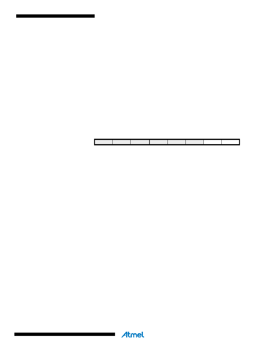
Bit
7
654
3
2
1
0
JTD
BODS(1)
BODSE(1)
PUD
–
IVSEL
IVCE
MCUCR
Read/Write
R/W
R
R/W
Initial Value
0
相关PDF资料 |
PDF描述 |
|---|---|
| VI-J0J-IX-B1 | CONVERTER MOD DC/DC 36V 75W |
| VI-JTZ-IY-F1 | CONVERTER MOD DC/DC 2V 20W |
| VI-JTZ-IX-F3 | CONVERTER MOD DC/DC 2V 30W |
| ATMEGA168PV-10MU | MCU AVR 16K FLASH 10MHZ 32-QFN |
| VI-J0H-IX-B1 | CONVERTER MOD DC/DC 52V 75W |
相关代理商/技术参数 |
参数描述 |
|---|---|
| ATMEGA164P | 制造商:ATMEL 制造商全称:ATMEL Corporation 功能描述:8-bit Microcontroller with 16/32/64K Bytes In-System Programmable Flash |
| ATMEGA164P_07 | 制造商:ATMEL 制造商全称:ATMEL Corporation 功能描述:8-bit Microcontroller with 16/32/64K Bytes In-System Programmable Flash |
| ATMEGA164P_0702 | 制造商:ATMEL 制造商全称:ATMEL Corporation 功能描述:8-bit Microcontroller with 16/32/64K Bytes In-System Programmable Flash |
| ATMEGA164P_08 | 制造商:ATMEL 制造商全称:ATMEL Corporation 功能描述:8-bit Microcontroller with 16/32/64K Bytes In-System Programmable Flash |
| ATMEGA164P_09 | 制造商:ATMEL 制造商全称:ATMEL Corporation 功能描述:8-bit Microcontroller with 16/32/64K Bytes In-System Programmable Flash |
发布紧急采购,3分钟左右您将得到回复。