- 您现在的位置:买卖IC网 > PDF目录12052 > ATMEGA164A-PU (Atmel)IC MCU AVR 16K 20MHZ 40PDIP PDF资料下载
参数资料
| 型号: | ATMEGA164A-PU |
| 厂商: | Atmel |
| 文件页数: | 155/160页 |
| 文件大小: | 0K |
| 描述: | IC MCU AVR 16K 20MHZ 40PDIP |
| 产品培训模块: | MCU Product Line Introduction megaAVR Introduction |
| 标准包装: | 14 |
| 系列: | AVR® ATmega |
| 核心处理器: | AVR |
| 芯体尺寸: | 8-位 |
| 速度: | 20MHz |
| 连通性: | I²C,SPI,UART/USART |
| 外围设备: | 欠压检测/复位,POR,PWM,WDT |
| 输入/输出数: | 32 |
| 程序存储器容量: | 16KB(8K x 16) |
| 程序存储器类型: | 闪存 |
| EEPROM 大小: | 512 x 8 |
| RAM 容量: | 1K x 8 |
| 电压 - 电源 (Vcc/Vdd): | 1.8 V ~ 5.5 V |
| 数据转换器: | A/D 8x10b |
| 振荡器型: | 内部 |
| 工作温度: | -40°C ~ 85°C |
| 封装/外壳: | 40-DIP(0.600",15.24mm) |
| 包装: | 管件 |
| 配用: | ATSTK600-RC05-ND - STK600 ROUTING CARD AVR |
第1页第2页第3页第4页第5页第6页第7页第8页第9页第10页第11页第12页第13页第14页第15页第16页第17页第18页第19页第20页第21页第22页第23页第24页第25页第26页第27页第28页第29页第30页第31页第32页第33页第34页第35页第36页第37页第38页第39页第40页第41页第42页第43页第44页第45页第46页第47页第48页第49页第50页第51页第52页第53页第54页第55页第56页第57页第58页第59页第60页第61页第62页第63页第64页第65页第66页第67页第68页第69页第70页第71页第72页第73页第74页第75页第76页第77页第78页第79页第80页第81页第82页第83页第84页第85页第86页第87页第88页第89页第90页第91页第92页第93页第94页第95页第96页第97页第98页第99页第100页第101页第102页第103页第104页第105页第106页第107页第108页第109页第110页第111页第112页第113页第114页第115页第116页第117页第118页第119页第120页第121页第122页第123页第124页第125页第126页第127页第128页第129页第130页第131页第132页第133页第134页第135页第136页第137页第138页第139页第140页第141页第142页第143页第144页第145页第146页第147页第148页第149页第150页第151页第152页第153页第154页当前第155页第156页第157页第158页第159页第160页
94
8272E–AVR–04/2013
ATmega164A/PA/324A/PA/644A/PA/1284/P
uses to increment (or decrement) its value. The Timer/Counter is inactive when no clock source
is selected. The output from the Clock Select logic is referred to as the timer clock (clk
T0).
The double buffered Output Compare Registers (OCR0A and OCR0B) are compared with the
Timer/Counter value at all times. The result of the compare can be used by the Waveform Gen-
erator to generate a PWM or variable frequency output on the Output Compare pins (OC0A and
OC0B). See Section “15.5” on page 95 for details. The Compare Match event will also set the
Compare Flag (OCF0A or OCF0B) which can be used to generate an Output Compare interrupt
request.
15.2.2
Definitions
Many register and bit references in this section are written in general form. A lower case “n”
replaces the Timer/Counter number, in this case 0. A lower case “x” replaces the Output Com-
pare Unit, in this case Compare Unit A or Compare Unit B. However, when using the register or
bit defines in a program, the precise form must be used, that is, TCNT0 for accessing
Timer/Counter0 counter value and so on.
The definitions in Table 15-1 are also used extensively throughout the document.
15.3
Timer/Counter Clock Sources
The Timer/Counter can be clocked by an internal or an external clock source. The clock source
is selected by the Clock Select logic which is controlled by the Clock Select (CS02:0) bits
located in the Timer/Counter Control Register (TCCR0B). For details on clock sources and pres-
caler, see ”Timer/Counter Prescaler” on page 156.
15.4
Counter Unit
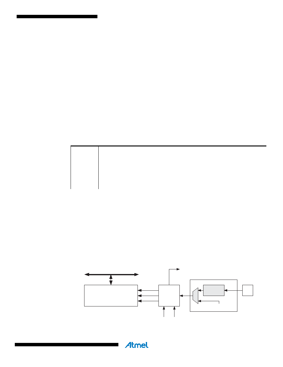
The main part of the 8-bit Timer/Counter is the programmable bi-directional counter unit. Figure
15-2 shows a block diagram of the counter and its surroundings.
Figure 15-2. Counter Unit block diagram.
Signal description (internal signals):
Table 15-1.
Definitions.
BOTTOM
The counter reaches the BOTTOM when it becomes 0x00.
MAX
The counter reaches its MAXimum when it becomes 0xFF (decimal 255).
TOP
The counter reaches the TOP when it becomes equal to the highest value in the
count sequence. The TOP value can be assigned to be the fixed value 0xFF
(MAX) or the value stored in the OCR0A Register. The assignment is depen-
dent on the mode of operation.
DATA BUS
TCNTn
Control Logic
count
TOVn
(Int.Req.)
Clock Select
top
Tn
Edge
Detector
( From Prescaler )
clk
Tn
bottom
direction
clear
相关PDF资料 |
PDF描述 |
|---|---|
| VI-J0J-IX-B1 | CONVERTER MOD DC/DC 36V 75W |
| VI-JTZ-IY-F1 | CONVERTER MOD DC/DC 2V 20W |
| VI-JTZ-IX-F3 | CONVERTER MOD DC/DC 2V 30W |
| ATMEGA168PV-10MU | MCU AVR 16K FLASH 10MHZ 32-QFN |
| VI-J0H-IX-B1 | CONVERTER MOD DC/DC 52V 75W |
相关代理商/技术参数 |
参数描述 |
|---|---|
| ATMEGA164P | 制造商:ATMEL 制造商全称:ATMEL Corporation 功能描述:8-bit Microcontroller with 16/32/64K Bytes In-System Programmable Flash |
| ATMEGA164P_07 | 制造商:ATMEL 制造商全称:ATMEL Corporation 功能描述:8-bit Microcontroller with 16/32/64K Bytes In-System Programmable Flash |
| ATMEGA164P_0702 | 制造商:ATMEL 制造商全称:ATMEL Corporation 功能描述:8-bit Microcontroller with 16/32/64K Bytes In-System Programmable Flash |
| ATMEGA164P_08 | 制造商:ATMEL 制造商全称:ATMEL Corporation 功能描述:8-bit Microcontroller with 16/32/64K Bytes In-System Programmable Flash |
| ATMEGA164P_09 | 制造商:ATMEL 制造商全称:ATMEL Corporation 功能描述:8-bit Microcontroller with 16/32/64K Bytes In-System Programmable Flash |
发布紧急采购,3分钟左右您将得到回复。