- 您现在的位置:买卖IC网 > PDF目录20392 > DC1472A (Linear Technology)BOARD DEMO LTM4618 PDF资料下载
参数资料
| 型号: | DC1472A |
| 厂商: | Linear Technology |
| 文件页数: | 11/24页 |
| 文件大小: | 0K |
| 描述: | BOARD DEMO LTM4618 |
| 软件下载: | LTM4618 Spice Model |
| 设计资源: | DC1472A Design Files DC1472A Schematic |
| 标准包装: | 1 |
| 系列: | µModule® |
| 主要目的: | DC/DC,步降 |
| 输出及类型: | 1,非隔离 |
| 输出电压: | 1.2V,1.5V,1.8V,2.5V,3.3V,5V |
| 电流 - 输出: | 6A |
| 输入电压: | 4.5 ~ 26.5 V |
| 稳压器拓扑结构: | 降压 |
| 频率 - 开关: | 500kHz |
| 板类型: | 完全填充 |
| 已供物品: | 板 |
| 已用 IC / 零件: | LTM4618 |
| 相关产品: | LTM4618IV#PBF-ND - IC DC-DC UMODULE BUCK 6A 84-LGA LTM4618EV#PBF-ND - IC DC-DC UMODULE BUCK 6A 84-LGA |
| 其它名称: | DC1472 DC1472-ND |
�� �
�
�LTM4618�
�APPLICATIONS� INFORMATION�
�Output� Capacitors�
�The� LTM4618� is� designed� for� low� output� voltage� ripple�
�noise.� The� bulk� output� capacitors� de?ned� as� C� OUT� are�
�chosen� with� low� enough� effective� series� resistance� (ESR)� to�
�meet� the� output� voltage� ripple� and� transient� requirements.�
�C� OUT� can� be� a� low� ESR� tantalum� capacitor,� a� low� ESR�
�polymer� capacitor� or� ceramic� capacitor.� The� typical� output�
�capacitance� range� is� from� 100μF� to� 300μF.� Additional� output�
�?ltering� may� be� required� by� the� system� designer� if� further�
�reduction� of� output� ripple� or� dynamic� transient� spikes� is�
�required.� Table� 4� shows� a� matrix� of� different� output� voltages�
�and� output� capacitors� to� minimize� the� voltage� droop� and�
�overshoot� during� a� 3A/μs� transient.� The� table� optimizes� the�
�total� equivalent� ESR� and� total� bulk� capacitance� to� optimize�
�the� transient� performance.� Stability� criteria� are� considered�
�in� the� Table� 4� matrix,� and� the� Linear� Technology� μModule�
�Power� Design� Tool� is� available� for� stability� analysis.� Mul-�
�tiphase� operation� will� reduce� effective� output� ripple� as� a�
�function� of� the� number� of� phases.� Application� Note� 77�
�discusses� this� noise� reduction� versus� output� ripple� cur-�
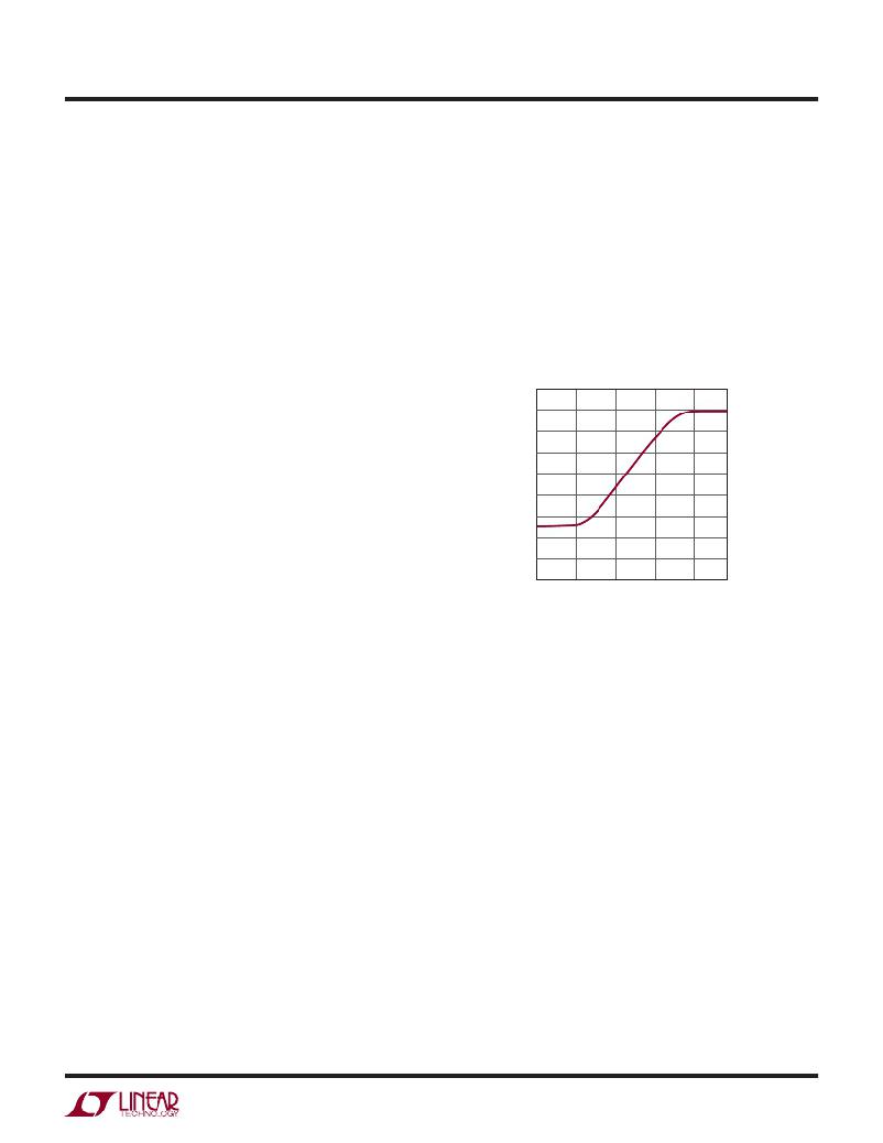
�pin� is� not� being� driven� by� an� external� clock� source,�
�the� FREQ� pin� can� program� the� controller’s� operating�
�frequency� from� 250kHz� to� 780kHz� by� connecting� a� re-�
�sistor� divider� as� shown� in� Figure� 21.� When� operating�
�below� 400kHz,� ensure� the� inductor� ripple� current� is� at�
�a� reasonable� level.� The� typical� frequency� is� 750kHz.�
�But� if� the� minimum� on-time� is� reached,� a� lower� frequency�
�needs� to� be� set� to� increase� the� turn-on� time.� Otherwise,� a�
�signi?cant� amount� of� cycle� skipping� can� occur� with� cor-�
�respondingly� larger� ripple� current� and� voltage� ripple.�
�900�
�800�
�700�
�600�
�500�
�400�
�300�
�200�
�100�
�rent� cancellation,� but� the� output� capacitance� should� be�
�considered� carefully� as� a� function� of� stability� and� transient�
�0�
�0�
�0.5�
�1� 1.5�
�FREQ� PIN� VOLTAGE� (V)�
�2�
�2.5�
�response.� The� Linear� Technology� μModule� Power� Design�
�Tool� can� calculate� the� output� ripple� reduction� as� the� number�
�of� implemented� phases� increases� by� N� times.�
�Mode� Selections� and� Phase-Locked� Loop�
�The� LTM4618� can� be� enabled� to� enter� high� ef?ciency�
�Burst� Mode� operation,� constant-frequency,� pulse-skipping�
�mode,� or� forced� continuous� conduction� mode.� To� select�
�the� forced� continuous� operation,� tie� the� MODE/PLLIN� pin�
�to� ground.� To� select� pulse-skipping� mode� of� operation,�
�tie� the� MODE/PLLIN� pin� to� INTV� CC� .� To� select� Burst� Mode�
�operation,� ?oat� the� pin.�
�A� phase-locked� loop� (PLL)� is� available� on� the� LTM4618�
�to� synchronize� the� internal� oscillator� to� an� external� clock�
�source� that� is� connected� to� the� MODE/PLLIN� pin.� The�
�incoming� clock� should� be� applied� before� the� regulator’s�
�RUN� pin� is� enabled.�
�Frequency� Selection�
�The� switching� frequency� of� the� LTM4618’s� controller�
�can� be� selected� using� a� DC� voltage.� If� the� MODE/PLLIN�
�4618� F03�
�Figure� 3.� Relationship� Between� Switching�
�Frequency� and� Voltage� at� the� FREQ� Pin�
�Frequency� Synchronization�
�The� MODE/PLLIN� pin� allows� the� LTM4618� to� be� syn-�
�chronized� to� an� external� clock� (between� 250kHz� to�
�780kHz)� and� the� internal� phase-locked� loop� allows� the�
�LTM4618� to� lock� onto� input� clock� phase� as� well.� When�
�operating� below� 400kHz,� ensure� the� inductor� ripple� cur-�
�rent� is� at� a� reasonable� level.� No� more� than� 50%� of� the�
�load� current� is� recommended.� The� FREQ� pin� has� the�
�onboard� loop� ?lter� for� the� PLL.� The� incoming� clock� must�
�be� applied� before� the� RUN� pin� is� enabled.� For� applica-�
�tions� powering� the� clock� source� from� the� LTM4618’s�
�INTV� CC� ,� the� RUN� pin� has� to� be� enabled� in� order� to� ac-�
�tivate� INTV� CC� for� the� clock� source.� In� this� situation� (see�
�Figure� 22)� the� TK/SS� pin� can� be� used� to� soft-start� the�
�regulator� for� 100ms� using� a� ≈� 0.22μF� capacitor.� This� will�
�allow� the� regulator� to� synchronize� to� the� right� frequency�
�before� the� regulator’s� inductor� ripple� current� peaks.�
�4618fa�
�11�
�相关PDF资料 |
PDF描述 |
|---|---|
| EBM15DTKS | CONN EDGECARD 30POS DIP .156 SLD |
| IR2136S | IC DRIVER BRIDGE 3-PHASE 28-SOIC |
| EL7156CS-T7 | IC PIN DRIVER 40MHZ 3ST 8-SOIC |
| 395-062-521-204 | CARD EDGE 62POS DL .100X.200 BLK |
| F750G108MDC | CAP TANT 1000UF 4V 20% 2917 |
相关代理商/技术参数 |
参数描述 |
|---|---|
| DC1477A | 功能描述:BOARD EVAL LTM4609 RoHS:否 类别:编程器,开发系统 >> 评估板 - DC/DC 与 AC/DC(离线)SMPS 系列:µModule® 标准包装:1 系列:- 主要目的:DC/DC,步降 输出及类型:1,非隔离 功率 - 输出:- 输出电压:3.3V 电流 - 输出:3A 输入电压:4.5 V ~ 28 V 稳压器拓扑结构:降压 频率 - 开关:250kHz 板类型:完全填充 已供物品:板 已用 IC / 零件:L7981 其它名称:497-12113STEVAL-ISA094V1-ND |
| DC1477B | 功能描述:BOARD EVAL LTM4609 RoHS:否 类别:编程器,开发系统 >> 评估板 - DC/DC 与 AC/DC(离线)SMPS 系列:µModule® 标准包装:1 系列:- 主要目的:DC/DC,步降 输出及类型:1,非隔离 功率 - 输出:- 输出电压:3.3V 电流 - 输出:3A 输入电压:4.5 V ~ 28 V 稳压器拓扑结构:降压 频率 - 开关:250kHz 板类型:完全填充 已供物品:板 已用 IC / 零件:L7981 其它名称:497-12113STEVAL-ISA094V1-ND |
| DC1483A | 制造商:Linear Technology 功能描述:EVAL BOARD, LTC3535 100mA SYNC STEP-UP R 制造商:Linear Technology 功能描述:EVAL BOARD, LTC3535 100mA SYNC STEP-UP REG; Silicon Manufacturer:Linear Technology; Silicon Core Number:LTC3535; Kit Application Type:Power Management; Kit Contents:Evaluation Board for LTC3535; Length:42mm |
| DC1485A | 功能描述:BOARD DAC LTC2757 RoHS:是 类别:编程器,开发系统 >> 评估板 - 数模转换器 (DAC) 系列:QuikEval™, SoftSpan™ 产品培训模块:Lead (SnPb) Finish for COTS Obsolescence Mitigation Program 标准包装:1 系列:- DAC 的数量:4 位数:12 采样率(每秒):- 数据接口:串行,SPI? 设置时间:3µs DAC 型:电流/电压 工作温度:-40°C ~ 85°C 已供物品:板 已用 IC / 零件:MAX5581 |
| DC1488A-A | 功能描述:BOARD DAC LTC2634-12 RoHS:是 类别:编程器,开发系统 >> 评估板 - 数模转换器 (DAC) 系列:QuikEval™ 产品培训模块:Lead (SnPb) Finish for COTS Obsolescence Mitigation Program 标准包装:1 系列:- DAC 的数量:4 位数:12 采样率(每秒):- 数据接口:串行,SPI? 设置时间:3µs DAC 型:电流/电压 工作温度:-40°C ~ 85°C 已供物品:板 已用 IC / 零件:MAX5581 |
发布紧急采购,3分钟左右您将得到回复。