- 您现在的位置:买卖IC网 > PDF目录20392 > DC1472A (Linear Technology)BOARD DEMO LTM4618 PDF资料下载
参数资料
| 型号: | DC1472A |
| 厂商: | Linear Technology |
| 文件页数: | 14/24页 |
| 文件大小: | 0K |
| 描述: | BOARD DEMO LTM4618 |
| 软件下载: | LTM4618 Spice Model |
| 设计资源: | DC1472A Design Files DC1472A Schematic |
| 标准包装: | 1 |
| 系列: | µModule® |
| 主要目的: | DC/DC,步降 |
| 输出及类型: | 1,非隔离 |
| 输出电压: | 1.2V,1.5V,1.8V,2.5V,3.3V,5V |
| 电流 - 输出: | 6A |
| 输入电压: | 4.5 ~ 26.5 V |
| 稳压器拓扑结构: | 降压 |
| 频率 - 开关: | 500kHz |
| 板类型: | 完全填充 |
| 已供物品: | 板 |
| 已用 IC / 零件: | LTM4618 |
| 相关产品: | LTM4618IV#PBF-ND - IC DC-DC UMODULE BUCK 6A 84-LGA LTM4618EV#PBF-ND - IC DC-DC UMODULE BUCK 6A 84-LGA |
| 其它名称: | DC1472 DC1472-ND |
�� �
�
�LTM4618�
�APPLICATIONS� INFORMATION�
�board,� and� is� really� the� sum� of� the� θ� JCbottom� and� the�
�thermal� resistance� of� the� bottom� of� the� part� through�
�the� solder� joints� and� through� a� portion� of� the� board.�
�The� board� temperature� is� measured� at� speci?ed� dis-�
�tance� from� the� package,� using� a� two� sided,� two� layer�
�board.� This� board� is� described� in� JESD� 51-9.�
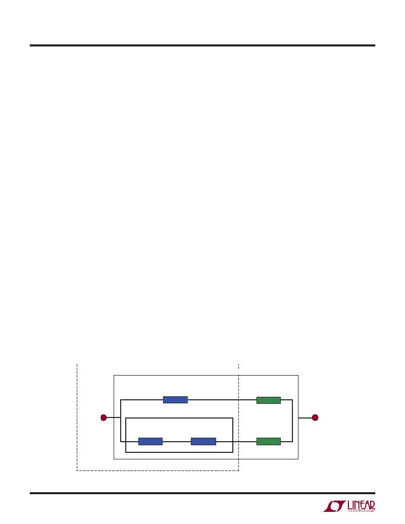
�A� graphical� representation� of� the� forementioned� thermal�
�resistances� is� given� in� Figure� 6;� blue� resistances� are�
�contained� within� the� μModule� regulator,� whereas� green�
�resistances� are� external� to� the� μModule� regulator.�
�As� a� practical� matter,� it� should� be� clear� to� the� reader� that�
�no� individual� or� sub-group� of� the� four� thermal� resistance�
�parameters� de?ned� by� JESD� 51-12� or� provided� in� the�
�Pin� Con?guration� section� replicates� or� conveys� normal�
�operating� conditions� of� a� μModule� regulator.� For� example,�
�in� actual� board-mounted� applications,� never� does� 100%�
�of� the� device’s� total� power� loss� (heat)� thermally� conduct�
�exclusively� through� the� top� or� exclusively� through� bot-�
�tom� of� the� μModule� regulator—as� the� standard� de?nes�
�for� θ� JCtop� and� θ� JCbottom� ,� respectively.� In� practice,� power�
�loss� is� thermally� dissipated� in� both� directions� away� from�
�the� package—granted,� in� the� absence� of� a� heat� sink� and�
�air?ow,� a� majority� of� the� heat� ?ow� is� into� the� board.�
�Within� a� SIP� (System-In-Package)� module,� be� aware� there�
�are� multiple� power� devices� and� components� dissipating�
�power,� with� a� consequence� that� the� thermal� resistances�
�relative� to� different� junctions� of� components� or� die� are� not�
�exactly� linear� with� respect� to� total� package� power� loss.� To�
�reconcile� this� complication� without� sacri?cing� modeling�
�simplicity—but� also,� not� ignoring� practical� realities—an�
�approach� has� been� taken� using� FEA� software� modeling�
�along� with� laboratory� testing� in� a� controlled-environment�
�chamber� to� reasonably� de?ne� and� correlate� the� thermal�
�resistance� values� supplied� in� this� data� sheet:� (1)� Initially,�
�FEA� software� is� used� to� accurately� build� the� mechanical�
�geometry� of� the� μModule� regulator� and� the� speci?ed� PCB�
�with� all� of� the� correct� material� coef?cients� along� with�
�accurate� power� loss� source� de?nitions;� (2)� this� model�
�simulates� a� software-de?ned� JEDEC� environment� consis-�
�tent� with� JSED51-9� to� predict� power� loss� heat� ?ow� and�
�temperature� readings� at� different� interfaces� that� enable�
�the� calculation� of� the� JEDEC-de?ned� thermal� resistance�
�values;� (3)� the� model� and� FEA� software� is� used� to� evalu-�
�ate� the� μModule� regulator� with� heat� sinks� and� air?ow;� (4)�
�having� solved� for� and� analyzed� these� thermal� resistance�
�values� and� simulated� various� operating� conditions� in� the�
�software� model,� a� thorough� laboratory� evaluation� replicates�
�the� simulated� conditions� with� thermocouples� within� a�
�controlled-environment� chamber� while� operating� the� device�
�at� the� same� power� loss� as� that� which� was� simulated.� An�
�outcome� of� this� process� and� due-diligence� yields� a� set�
�of� derating� curves� provided� in� other� sections� of� this� data�
�sheet.� After� these� laboratory� tests� have� been� performed�
�and� correlated� to� the� μModule� package� model,� then� the�
�θ� JB� and� θ� BA� are� summed� together� to� correlate� quite� well�
�with� the� μModule� package� model� with� no� air� ?ow� or� heat�
�sinking� in� a� properly� de?ne� chamber.� This� θ� JB� +� θ� BA� value�
�is� shown� in� the� Pin� Con?guration� section� and� should� ac-�
�curately� equal� the� θ� JA� value� because� approximately� 100%�
�of� power� loss� ?ows� from� the� junction� through� the� board�
�into� ambient� with� no� air?ow� or� top� mounted� heat� sink.�
�JUNCTION-TO-AMBIENT RESISTANCE (JESD 51-9 DEFINED BOARD)�
�JUNCTION-TO-CASE� (TOP)�
�RESISTANCE�
�CASE� (TOP)-TO-AMBIENT�
�RESISTANCE�
�JUNCTION�
�JUNCTION-TO-BOARD� RESISTANCE�
�At�
�JUNCTION-TO-CASE�
�(BOTTOM)� RESISTANCE�
�CASE� (BOTTOM)-TO-BOARD�
�RESISTANCE�
�BOARD-TO-AMBIENT�
�RESISTANCE�
�4618� F06�
�μMODULE� DEVICE�
�Figure� 6.� Graphical� Representation� of� JESD51-12� Thermal� Coef?cients�
�4618fa�
�14�
�相关PDF资料 |
PDF描述 |
|---|---|
| EBM15DTKS | CONN EDGECARD 30POS DIP .156 SLD |
| IR2136S | IC DRIVER BRIDGE 3-PHASE 28-SOIC |
| EL7156CS-T7 | IC PIN DRIVER 40MHZ 3ST 8-SOIC |
| 395-062-521-204 | CARD EDGE 62POS DL .100X.200 BLK |
| F750G108MDC | CAP TANT 1000UF 4V 20% 2917 |
相关代理商/技术参数 |
参数描述 |
|---|---|
| DC1477A | 功能描述:BOARD EVAL LTM4609 RoHS:否 类别:编程器,开发系统 >> 评估板 - DC/DC 与 AC/DC(离线)SMPS 系列:µModule® 标准包装:1 系列:- 主要目的:DC/DC,步降 输出及类型:1,非隔离 功率 - 输出:- 输出电压:3.3V 电流 - 输出:3A 输入电压:4.5 V ~ 28 V 稳压器拓扑结构:降压 频率 - 开关:250kHz 板类型:完全填充 已供物品:板 已用 IC / 零件:L7981 其它名称:497-12113STEVAL-ISA094V1-ND |
| DC1477B | 功能描述:BOARD EVAL LTM4609 RoHS:否 类别:编程器,开发系统 >> 评估板 - DC/DC 与 AC/DC(离线)SMPS 系列:µModule® 标准包装:1 系列:- 主要目的:DC/DC,步降 输出及类型:1,非隔离 功率 - 输出:- 输出电压:3.3V 电流 - 输出:3A 输入电压:4.5 V ~ 28 V 稳压器拓扑结构:降压 频率 - 开关:250kHz 板类型:完全填充 已供物品:板 已用 IC / 零件:L7981 其它名称:497-12113STEVAL-ISA094V1-ND |
| DC1483A | 制造商:Linear Technology 功能描述:EVAL BOARD, LTC3535 100mA SYNC STEP-UP R 制造商:Linear Technology 功能描述:EVAL BOARD, LTC3535 100mA SYNC STEP-UP REG; Silicon Manufacturer:Linear Technology; Silicon Core Number:LTC3535; Kit Application Type:Power Management; Kit Contents:Evaluation Board for LTC3535; Length:42mm |
| DC1485A | 功能描述:BOARD DAC LTC2757 RoHS:是 类别:编程器,开发系统 >> 评估板 - 数模转换器 (DAC) 系列:QuikEval™, SoftSpan™ 产品培训模块:Lead (SnPb) Finish for COTS Obsolescence Mitigation Program 标准包装:1 系列:- DAC 的数量:4 位数:12 采样率(每秒):- 数据接口:串行,SPI? 设置时间:3µs DAC 型:电流/电压 工作温度:-40°C ~ 85°C 已供物品:板 已用 IC / 零件:MAX5581 |
| DC1488A-A | 功能描述:BOARD DAC LTC2634-12 RoHS:是 类别:编程器,开发系统 >> 评估板 - 数模转换器 (DAC) 系列:QuikEval™ 产品培训模块:Lead (SnPb) Finish for COTS Obsolescence Mitigation Program 标准包装:1 系列:- DAC 的数量:4 位数:12 采样率(每秒):- 数据接口:串行,SPI? 设置时间:3µs DAC 型:电流/电压 工作温度:-40°C ~ 85°C 已供物品:板 已用 IC / 零件:MAX5581 |
发布紧急采购,3分钟左右您将得到回复。