- 您现在的位置:买卖IC网 > PDF目录171212 > DP5Z2MW16PH3-15C 2M X 16 FLASH 5V PROM MODULE, 120 ns, QFP48 PDF资料下载
参数资料
| 型号: | DP5Z2MW16PH3-15C |
| 元件分类: | PROM |
| 英文描述: | 2M X 16 FLASH 5V PROM MODULE, 120 ns, QFP48 |
| 封装: | HERMETIC SEALED, CERAMIC, GULLWING, MODULE, SLCC-48 |
| 文件页数: | 17/21页 |
| 文件大小: | 4549K |
| 代理商: | DP5Z2MW16PH3-15C |
Dense-Pac Microsystems, Inc.
DP5Z2MW16Pn3
PRELIMINARY
PAGE PROGRAM
To initiate Page Program mode, a three-cycle command sequence
is required. There are two “unlock” write cycles. These are
followed by writing the page program command - A0H.
After three-cycle command sequence is given, a word load is
performed by applying a low pulse on the WE or CE input with CE
or WE low (respectively) and OE high. The address is latched on
the falling edge of CE or WE, whichever occurs last. The data is
latched by the first rising edge of CE or WE. Maximum of 64 words
of data may be loaded into each page by the same procedures as
outlined in the page program section below.
WORD LOAD
Word loads are used to enter the 64 words of a page to be
programmed. A word load is performed by applying a low pulse
on the WE or CE input CE or WE low respectively) and OE high.
The address is latched on the falling edge of CE or WE, whichever
occurs last. The data is latched by the first rising edge of CE or WE.
PROGRAM
Any page to be programmed should have the page in the erase
state first, i.e. performing sector erase is suggested before page
programming can be performed.
The device is programmed on a page basis. If a word of data within
a page is to be changed, data for the entire page can be loaded
into the device. Any word that is not loaded during the
programming of its page will be still in the erase state (i.e. FFH).
Once the words of a page are loaded into the device, they are
simultaneously programmed during the internal programming
period. After the first data word has been loaded into the device,
successive words are entered in the same manner. Each new word
to be programmed must have its high to low transition on WE (or
CE) within 30
s of the low to high transition of WE (or CE) of the
preceding word. A6 to A19 specify the page address, i.e. the
device is page-aligned on 64 words boundary The page address
must be valid during each high to low transition of WE or CE. A0
to A5 specify the word address within the page. The word may be
loaded in any order; sequential loading is not required. If a high
to low transition of CE or WE is not detected within 100
s of the
last low to high transition, the load period will end and the internal
programming period will start. The auto page program terminates
when status on I/O7 is “1" at which time the device stays at read
status register mode until the CIR contents are altered by a valid
command sequence. (Refer to Table 2 & 5 and Figure 1, 6 & 7)
CHIP ERASE
Chip erase is a six-bus cycle operation. There are two “unlock”
write cycles. These are followed by writing the “set-up” command
- 80H. Two more “unlock” write cycles are then followed by the
chip erase command - 10H.
Chip erase does not require the user to program the device prior
to erase.
The automatic erase begins on the rising edge of the last WE pulse
in the command sequence and terminates when the status on I/O7
is “1" at which time the device stays at read status register mode
until the CIR contents are altered by a valid command sequence.
(Refer to Tables 2 & 5 and Figures 2, 6 & 8)
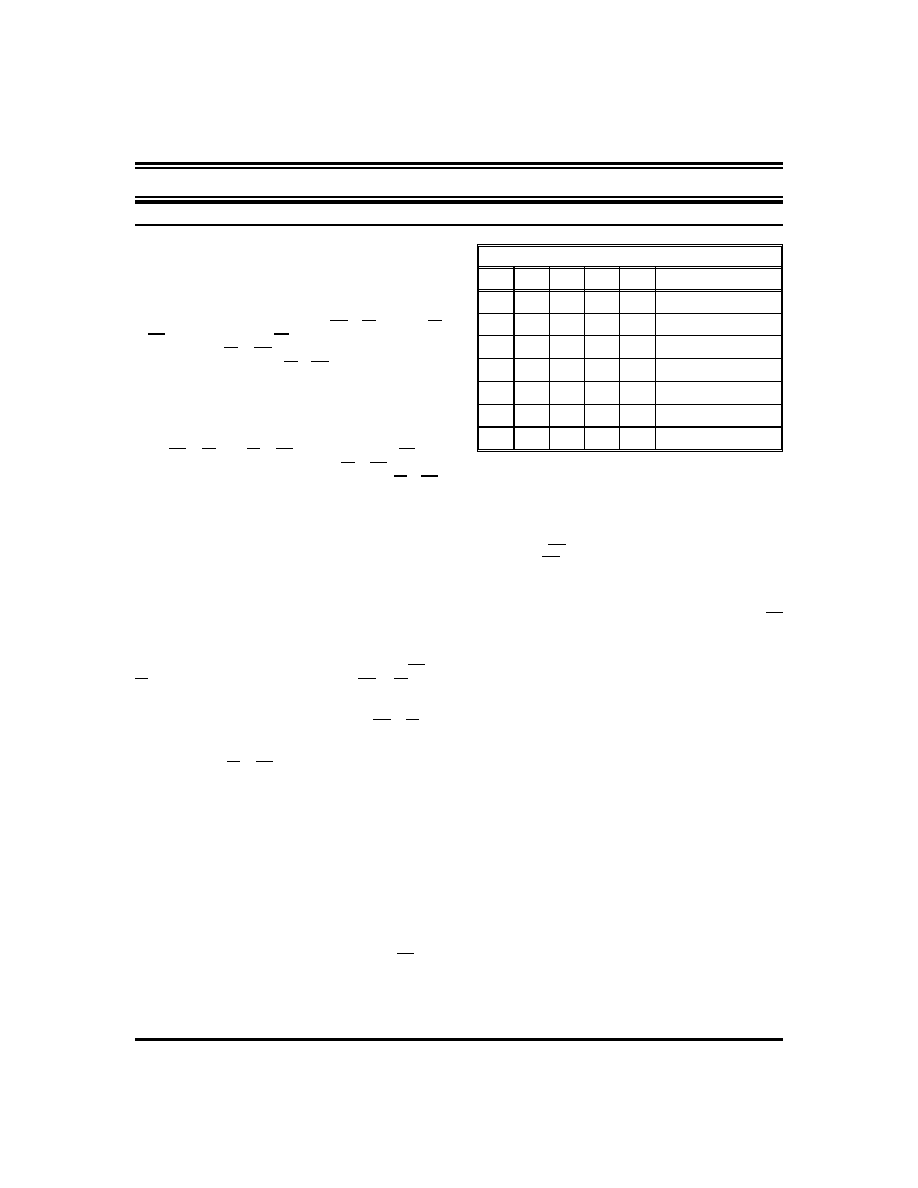
Table 4: Sector Address*
A19
A18
A17
A16 Address Range [A0-A15]
SA0
0
00000H—0FFFFH
SA1
0
1
10000H—1FFFFH
SA2
0
1
0
20000H—2FFFFH
SA3
0
1
30000H—3FFFFH
SA4
0
1
0
40000H—4FFFFH
...
....
...
................
SA15
1
F0000H—FFFFFH
* Per 1 Meg x 16 device.
SECTOR ERASE
Sector erase is a six-bus cycle operation. There are two “unlock”
write cycles. These are followed by writing the set-up command
- 80H. Two more “unlock” write cycles are then followed by the
sector erase command - 30H. The sector address is latched on the
falling edge of WE, while the command (data) is latched on the
rising edge of WE.
Sector erase does not require the user to program the device prior
to erase. The system is not required to provide any controls or
timings during these operations.
The automatic sector erase begins on the rising edge of the last WE
pulse in the command sequence and terminates when the status
on I/O7 is “1" at which time the device stays at read status register
mode. The device remains enabled for read status register mode
until the CIR contents are altered by a valid command sequence.
(Refer to Tables 2, & 5 and Figures 3, 4, 6 & 8)
ERASE SUSPEND
This command only has meaning while the WSM is executing
SECTOR or CHIP erase operations, and therefore will only be
responded to during SECTOR or CHIP erase operation. After this
command has been executed, the CIR will initiate the WSM to
suspend erase operations, and then return to Read Status Register
mode. The WSM will set the I/O6 bit to a “1". Once the WSM has
reached the Suspend state, the WSM will set I/O7 bit to a “1". At
this time, WSM allows CIR to respond to the Read Array, Read
Status Register, Abort and Erase Resume commands only. In this
mode, the CIR will not respond to any other commands. the WSM
will continue to run, idling in the SUSPEND state, regardless of the
state of all input control pins.
ERASE RESUME
This command will cause the CIR to clear the suspend state and
set the I/O6 to a “0", but only in an Erase Suspend command was
previously used. Erase Resume will not have any effect in all other
conditions.
READ STATUS REGISTER COMMAND
The module contains a Status Register which may be read to
determine when a program or erase operation is complete, and
whether that operation completed successfully. The status register
may be read at any time by writing the Read Status command to
the CIR. After writing this command, all subsequent read
operations output data from the status register, until another valid
command is written to the CIR. A Read Array command must be
written to the CIR to return to the Read Array mode.
30A161-22
REV. B
5
相关PDF资料 |
PDF描述 |
|---|---|
| DP83957 | |
| DP83957VF | REPEATER MANAGEMENT|QFP|80PIN|PLASTIC |
| DP83959AVUL | LAN Hub Controller |
| DP83BC04BJ | Single 8-bit Bus Transceiver |
| DP83BC04BN | Single 8-bit Bus Transceiver |
相关代理商/技术参数 |
参数描述 |
|---|---|
| DP600-GRAY-50CC | 制造商:3M Electronic Products Division 功能描述:62265250308 3M(TM)S/W(TM) CONC 制造商:3M Electronic Products Division 功能描述:CNCRTE RPR DP-600 NON-SAG GRY 50 制造商:3M Electronic Products Division 功能描述:S/W CONCRETE RPR NON-SAG,GR,50CC SYRG |
| DP-600-Non-Sag-12oz | 功能描述:化学物质 S/W CNCRT REPAIR, NN-SAG,GRAY,12OZ CRT RoHS:否 制造商:3M Electronic Specialty 产品:Adhesives 类型:Epoxy Compound 大小:1.7 oz 外壳:Plastic Tube |
| DP-600-SELF-LEVEL-50ML | 制造商:3M Electronic Products Division 功能描述:Concrete Repair Gray Self-Leveling, 50 mL Syringe |
| DP-600-SELF-LEVEL-8.4OZ | 制造商:3M Electronic Products Division 功能描述:Concrete Repair Gray Self-Leveling, 8.4 oz Cartridge |
| DP600SL | 制造商:3M Electronic Products Division 功能描述:CONCRETE REPAIR KIT |
发布紧急采购,3分钟左右您将得到回复。