- 您现在的位置:买卖IC网 > PDF目录171212 > DP5Z2MW16PH3-15C 2M X 16 FLASH 5V PROM MODULE, 120 ns, QFP48 PDF资料下载
参数资料
| 型号: | DP5Z2MW16PH3-15C |
| 元件分类: | PROM |
| 英文描述: | 2M X 16 FLASH 5V PROM MODULE, 120 ns, QFP48 |
| 封装: | HERMETIC SEALED, CERAMIC, GULLWING, MODULE, SLCC-48 |
| 文件页数: | 18/21页 |
| 文件大小: | 4549K |
| 代理商: | DP5Z2MW16PH3-15C |
DP5Z2MW16Pn3
Dense-Pac Microsystems, Inc.
PRELIMINARY
The status register bits are output on I/O2 - I/O7 (Table 5),
I/O0-I/O1 and I/O8-I/O15 is set to 0H.
It should be noted that the status register are latched on the falling
edge of OE or CE whichever occurs last in the read cycle. This
prevents possible bus errors which might occur if the contents of
the status register change while reading the status register. CE or
OE must be toggled with each subsequent status read, or the
completion of a program or erase operation will not be evident.
The Status Register is the interface between the microprocessor
and the Write State Machine (WSM). When the WSM is active,
this register will indicate the status of the WSM, and will also hold
the bits indicating whether or not the WSM was successful in
performing the desired operation. The WSM sets status bits four
through seven and clears bits six and seven, but cannot clear status
bits four and five. If Erase fail or Program fail status bit is detected,
the Status Register is not cleared until the Clear Status Register
command is written. The device automatically outputs Status
Register data when read after Chip Erase, Sector Erase, Page
Program or Read Status Command write cycle. the default state
of the Status Register after power-up and return from deep
power-down mode is (I/O7, I/O6, I/O5, I/O4) = 1000B. I/O3 =
0 or 1 depends on sector-protect status, can not be changed by
Clear Status Register Command or Write State Machine. I/O2 =
0 or 1 depends on Sleep status, During Sleep mode or Abort mode
I/O2 is set to “1"; I/O2 is reset to ”0" by Read Array command.
CLEAR STATUS REGISTER
The Erase fail status bit (I/O5) and Program fail status bit (I/O4) are
set by the write state machine, and can only be reset by the system
software. These bits can indicate various failure conditions (see
Table 5). By allowing the system software to control the resetting
of these bits, several operations may be performed (such as
cumulatively programming several pages or erasing multiple blocks
in sequence). The Status register may then be read to determine
if an error occurred during that programming or erasing series. This
adds flexibility to the way the device may be programmed or
erased. Additionally, once the program (erase) fail bit happens
, the
program (erase) operation can not be performed further. The
program (erase) fail bit must be reset by system software before
further page program or sector (chip) erase are attempted. To clear
the status register, the Clear Status Register command is written to
the CIR. Then, any other command may be issued to the CIR.
Note again that before a read cycle can be initiated, a Read
command must be written to the CIR to specify whether the read
data is to come from the Array, Status Register or Silicon ID.
SLEEP MODE
The device features two software controlled low-power modes:
Sleep and Abort modes. Sleep mode is allowable during any
current operations except that once Suspend command is issued,
Sleep command is ignored. Abort mode is executed only during
page Programming and Chip/Sector Erase mode.
To activate Sleep mode, a three-bus cycle operation is required.
C0H command (refer to Table 2) puts the device in the Sleep mode.
Once in the Sleep mode and CMOS input level applied, the power
of the device is reduced to deep power-down current levels. The
only threshold condition, input leakage, and output leakage.
The Sleep command allows the device to COMPLETE current
operations before going into Sleep mode. Once current operation
is done, device stays at read status register mode. The status
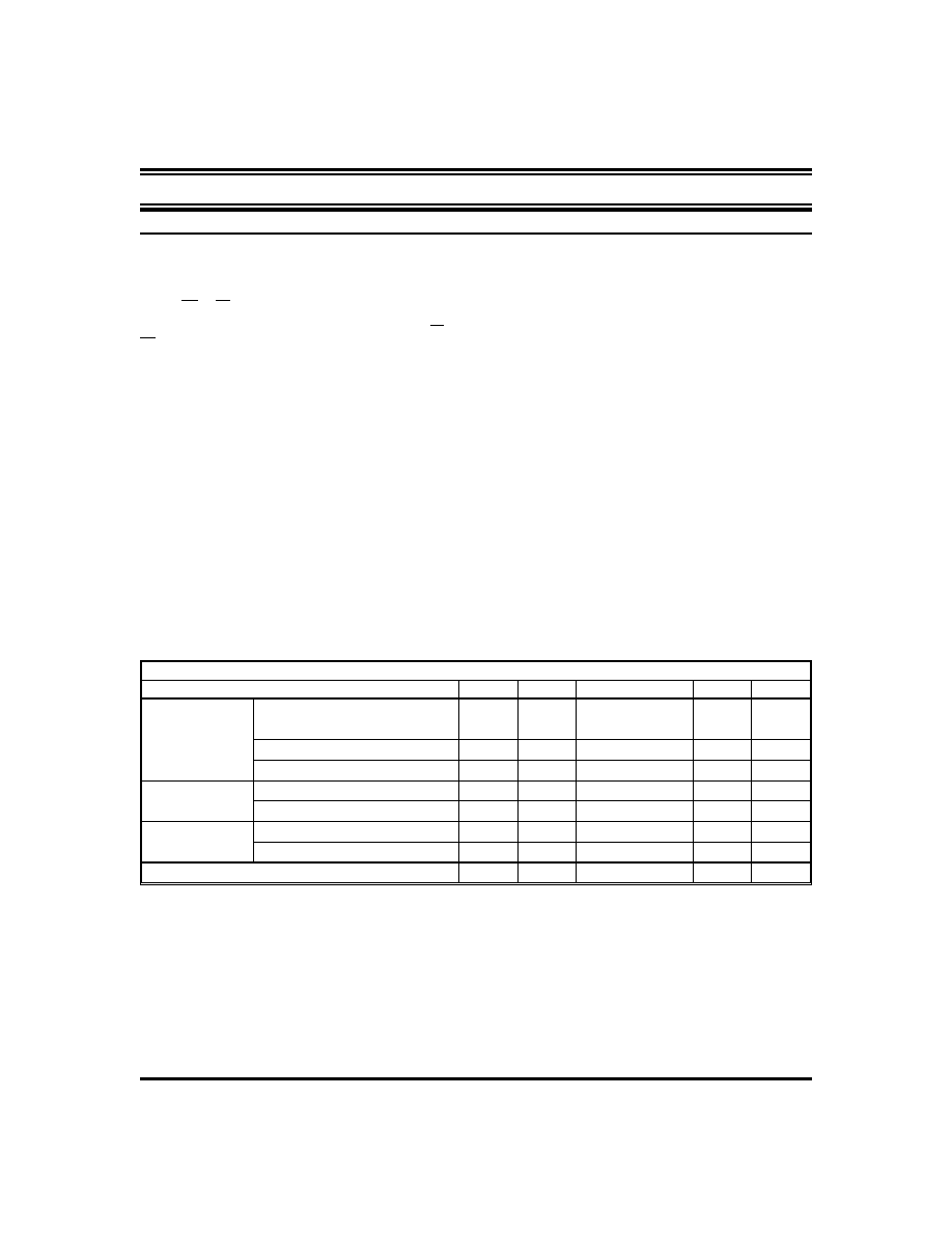
Table 5: Status Register
STATUS
I/O7
I/O6
I/O5
I/O4
I/O3
I/O2
IN PROGRESS
PROGRAM a, b, f
0
0/1
ERASE a, c, f
0
0/1
SUSPEND (NOT COMPLETE) a, d, f
0
1
0
0/1
SUSPEND (COMPLETE) a, d, f
1
0
0/1
COMPLETE
PROGRAM a, b, f
1
0
0/1
ERASE a, c, f
1
0
0/1
FAIL
PROGRAM a, e, f
1
0
1
0/1
ERASE a, e, f
1
0
1
0
0/1
AFTER CLEARING STATUS REGISTER f
1
0
0/1
Note ‘g’
NOTES:
a. I/O7: Write State Machine Status
1 = Ready, 0 = Busy
I/O6: Erase Suspend Status
1 = Suspend, 0 = No Suspend
I/O5: Erase Fail Status
1 = Fail in Erase, 0 = Successful Erase
I/O4: Program Fail Status
1 = Fail in Program, 0 = Successful Program
I/O3: Sector-Protect Status (Not Used)
I/O2: Sleep Status
1 = Device in Sleep Status, 0 = Device Not in Sleep Status
I/O1 - I/O0 = Reserved for further enhancements.
These bits are reserved for future use; mask them out when polling
the Status Register.
b. Program Status is for the status during Page Programming or Sector
Unprotect mode.
c. Erase Status is for the status during Sector/Chip Erase or Sector
Protection mode.
d. Suspend Status is for both Sector and Chip Erase mode.
e. Fail Status bit (I/O4 or I/O5) is provided during Page Program or
Sector/Chip Erase modes respectively.
f. I/O2 = 0 or 1 depends on whether device is in the Sleep mode or
not.
g. Once in the Sleep mode, I/O2 is set to “1", and is reset by read array
command only.
30A161-22
REV. B
6
相关PDF资料 |
PDF描述 |
|---|---|
| DP83957 | |
| DP83957VF | REPEATER MANAGEMENT|QFP|80PIN|PLASTIC |
| DP83959AVUL | LAN Hub Controller |
| DP83BC04BJ | Single 8-bit Bus Transceiver |
| DP83BC04BN | Single 8-bit Bus Transceiver |
相关代理商/技术参数 |
参数描述 |
|---|---|
| DP600-GRAY-50CC | 制造商:3M Electronic Products Division 功能描述:62265250308 3M(TM)S/W(TM) CONC 制造商:3M Electronic Products Division 功能描述:CNCRTE RPR DP-600 NON-SAG GRY 50 制造商:3M Electronic Products Division 功能描述:S/W CONCRETE RPR NON-SAG,GR,50CC SYRG |
| DP-600-Non-Sag-12oz | 功能描述:化学物质 S/W CNCRT REPAIR, NN-SAG,GRAY,12OZ CRT RoHS:否 制造商:3M Electronic Specialty 产品:Adhesives 类型:Epoxy Compound 大小:1.7 oz 外壳:Plastic Tube |
| DP-600-SELF-LEVEL-50ML | 制造商:3M Electronic Products Division 功能描述:Concrete Repair Gray Self-Leveling, 50 mL Syringe |
| DP-600-SELF-LEVEL-8.4OZ | 制造商:3M Electronic Products Division 功能描述:Concrete Repair Gray Self-Leveling, 8.4 oz Cartridge |
| DP600SL | 制造商:3M Electronic Products Division 功能描述:CONCRETE REPAIR KIT |
发布紧急采购,3分钟左右您将得到回复。