- 您现在的位置:买卖IC网 > PDF目录97909 > EM6617SO24A 30V N-Channel PowerTrench MOSFET PDF资料下载
参数资料
| 型号: | EM6617SO24A |
| 元件分类: | MOSFETs |
| 英文描述: | 30V N-Channel PowerTrench MOSFET |
| 中文描述: | 30V的N沟道的PowerTrench MOSFET的 |
| 文件页数: | 19/67页 |
| 文件大小: | 824K |
| 代理商: | EM6617SO24A |
第1页第2页第3页第4页第5页第6页第7页第8页第9页第10页第11页第12页第13页第14页第15页第16页第17页第18页当前第19页第20页第21页第22页第23页第24页第25页第26页第27页第28页第29页第30页第31页第32页第33页第34页第35页第36页第37页第38页第39页第40页第41页第42页第43页第44页第45页第46页第47页第48页第49页第50页第51页第52页第53页第54页第55页第56页第57页第58页第59页第60页第61页第62页第63页第64页第65页第66页第67页
EM6617
03/02 REV. C/442
Copyright
2002, EM Microelectronic-Marin SA
26
www.emmicroelectronic.com
For instance, loading the counter in up count mode with hex 000 and the comparator with hex C52 which will
be identified as :
- bits[11:10] are limiting the counter to limits to 4 bits length, =03
(BitSel[1,0])
- bits [9:4] are the unused counter bits = hex 05 (bin 000101),
(number of PWM pulses)
- bits [3:0] (comparator value = 2).
(length of PWM pulse)
Thus after 5 PWM-pulses of 2 clocks cycles length the Counter generates an IRQComp and stops.
The same example with SelIntFull=0 (limited bit compare) will produce an unlimited number of PWM at a length
of 2 clock cycles.
8.5.1 How the PWM Generator works.
For Up Count Mode
; Setting the counter in up count and PWM mode the PB[3] PWM output is defined to be 0
(EnComp=0 forces the PWM output to 0 in upcount mode, 1 in downcount). Each Roll Over will set the output
to ‘1’ and each Compare Match will set it back to ‘0’. The Compare Match for PWM always only works on the
defined counter length. This, independent of the SelIntFull setting which is valid only for the IRQ generation.
Refer also to the compare setup in chapter 8.4.
In above example the PWM starts counting up on hex 0,
2 cycles later compare match -> PWM to ‘0’,
14 cycles later roll over -> PWM to ‘1’
2 cycles later compare match -> PWM to ‘0’ , etc. until the completion of the 5 pulses.
The normal IRQ generation remains on during PWM output. If no IRQ’s are wanted, the corresponding masks
need to be set.
In Down Count Mode
everything is inverted. The PWM output starts with the ‘1’ value. Each Roll Over will set
the output to ‘0’ and each Compare Match will set it back to ‘1’. For limited pulse generation one must load the
complementary pulse number value. I.e. for 5 pulses counting on 4 bits load bits[9 :4] with hex 3A (bin 111010).
8.5.2 PWM Characteristics
PWM resolution is
: 10bits (1024 steps), 8bits (256 steps), 6bits (64 steps) or 4 bits (16 steps)
the minimal signal period is
: 16 (4-bit) x Fmax*
-> 16 x 1/Ck[15]
-> 977 s
(32 KHz)
the maximum signal period is
: 1024 x Fmin*
-> 1024 x 1/Ck[1]
-> 1024 s
(32 KHz)
the minimal pulse width is
: 1 bit
-> 1 x 1/Ck[15]
-> 61 s
(32 KHz)
* This values are for Fmax or Fmin derived from the internal system clock (32kHz). Much shorter (and longer)
PWM pulses can be achieved by using the port A as frequency input.
One must not use a compare value of hex 0 in up count mode nor a value of hex 3FF (or FF,3F, F if limited bit
compare) in downcount mode.
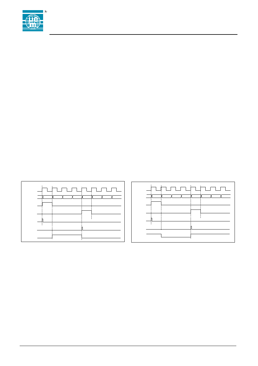
Figure 20. PWM Output in Up Count Mode
Data+2
Data+1
Data-1
Data
...
001
000
03F
03E
PWM output
IRQComp
IRQCount0
Compare
Roll-over
Count[9 :0]
Clock
Figure 21. PWM Output in Down Count Mode
Data-2
Data-1
Data+1
Data
...
3FE
3FF
000
001
PWM output
IRQComp
IRQCount0
Compare
Roll-over
Count[9 :0]
Clock
相关PDF资料 |
PDF描述 |
|---|---|
| EM6617SO24B | 30V N-Channel PowerTrench MOSFET |
| EM6617SO28A | Advanced Synchronous Rectified Buck MOSFET Drivers with Pre-POR OVP; Temperature Range: 0°C to 70°C; Package: 8-EPSOIC T&R |
| EM6617SO28B | Advanced Synchronous Rectified Buck MOSFET Drivers with Pre-POR OVP; Temperature Range: -40°C to 85°C; Package: 8-EPSOIC T&R |
| EM6617TP28A | Advanced Synchronous Rectified Buck MOSFET Drivers with Pre-POR OVP; Temperature Range: 0°C to 70°C; Package: 8-EPSOIC T&R |
| EM6617TP28B | Advanced Synchronous Rectified Buck MOSFET Drivers with Pre-POR OVP; Temperature Range: -40°C to 85°C; Package: 8-EPSOIC T&R |
相关代理商/技术参数 |
参数描述 |
|---|---|
| EM6617SO24B | 制造商:未知厂家 制造商全称:未知厂家 功能描述:Microcontroller |
| EM6617SO28A | 制造商:未知厂家 制造商全称:未知厂家 功能描述:Microcontroller |
| EM6617SO28B | 制造商:未知厂家 制造商全称:未知厂家 功能描述:Microcontroller |
| EM6617TP28A | 制造商:未知厂家 制造商全称:未知厂家 功能描述:Microcontroller |
| EM6617TP28B | 制造商:未知厂家 制造商全称:未知厂家 功能描述:Microcontroller |
发布紧急采购,3分钟左右您将得到回复。