- 您现在的位置:买卖IC网 > PDF目录67504 > FM4005-G SPECIALTY CONSUMER CIRCUIT, PDSO14 PDF资料下载
参数资料
| 型号: | FM4005-G |
| 元件分类: | 消费家电 |
| 英文描述: | SPECIALTY CONSUMER CIRCUIT, PDSO14 |
| 封装: | GREEN, MS-012AB, SOIC-14 |
| 文件页数: | 20/23页 |
| 文件大小: | 244K |
| 代理商: | FM4005-G |
N
O
T R
EC
O
M
EN
D
ED
FO
R
N
EW
D
ES
IG
N
S
Al
te
rn
at
iv
es
: F
M
31
27
2
(5
V)
or
FM
31
L2
72
(3
V)
FM4005
Rev. 2.4
Jan. 2010
Page 6 of 23
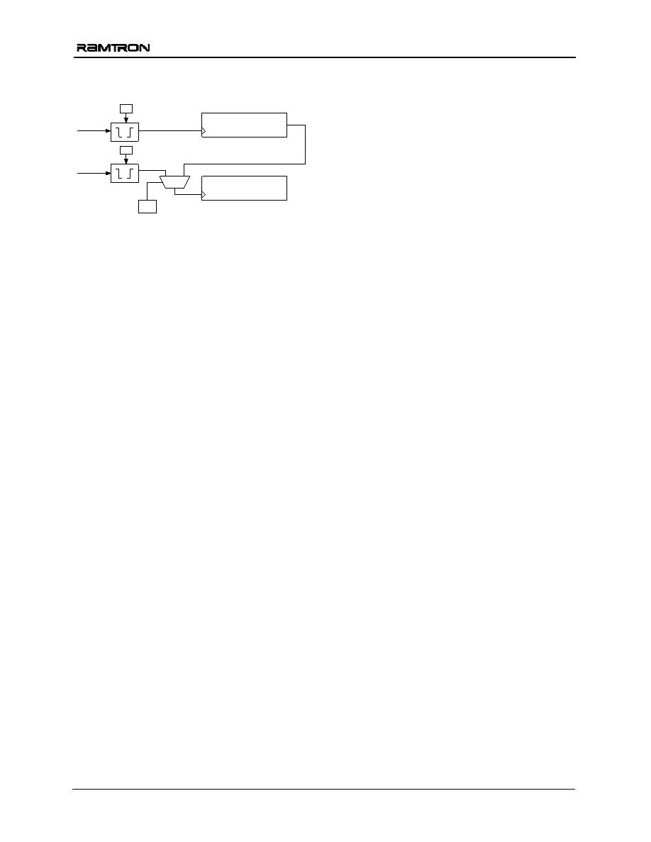
Counter 2 Polarity is C2P, bit 1; the Cascade Control
is CC, bit 2; and the Read Counter bit is RC bit 3.
Figure 6. Event Counter
The polarity bits must be set prior to setting the
counter value(s). If a polarity bit is changed, the
counter may inadvertently increment. If the counter
pins are not being used, tie them to ground.
Serial Number
A memory location to write a 64-bit serial number is
provided. It is a writeable nonvolatile register that
can be locked by the user once the serial number is
set. The serial number registers can be written an
unlimited number of times. However once the lock bit
is set the values cannot be altered and the lock
cannot be removed. Once locked the serial number
registers can still be read by the system.
The serial number is located in registers 11h to 18h.
The lock bit is SNL, register 0Bh, bit 7. Setting the
SNL bit to a 1 disables writes to the serial number
registers, and the SNL bit cannot be cleared.
Real-time Clock Operation
The real-time clock (RTC) is a timekeeping device
that
can
be
battery
or
capacitor
backed
for
permanently-powered operation. It offers a software
calibration feature that allows high accuracy.
The RTC consists of an oscillator, clock divider, and
a register system for user access. It divides down the
32.768 kHz time-base and provides a minimum
resolution of seconds (1Hz). Static registers provide
the user with read/write access to the time values. It
includes registers for seconds, minutes, hours, day-
of-the-week, date, months, and years. A block
diagram (Figure 7) illustrates the RTC function.
The
user
registers
are
synchronized
with
the
timekeeper core using R and W bits in register 00h
described below. Changing the R bit from 0 to 1
transfers timekeeping information from the core into
holding registers that can be read by the user. If a
timekeeper update is pending while R is set, then the
core will be updated prior to loading the user
registers. The registers are frozen and will not be
updated again until the R bit is cleared to 0. R is used
for reading the time.
Setting the W bit to 1 locks the user registers.
Clearing it to 0 causes the values in the user registers
to be loaded into the timekeeper core. W is used for
writing new time values. Users should be certain not
to load invalid values, such as FFh, to the
timekeeping registers. Updates to the timekeeping
core occur continuously except when locked.
Backup Power
The real-time clock/calendar is intended to be
permanently powered. When the primary system
power fails, the voltage on the VDD pin will drop.
When VDD drops below 2.5V, the RTC (and event
counters) will switch to the backup power supply on
VBAK. The clock uses very little current which
maximizes battery or capacitor life.
When inserting a battery into a system board,
higher-than-normal battery drain may occur. It is
recommended
that
your
system
power-up
procedure complies with one of the following:
Scenario #1
a) Apply Vdd to board.
b) Insert battery. At this point, IBAK is zero.
c) When VDD is powered down, the IBAK current
will be less than 1A.
Scenario #2
a) Insert battery without power to board (VDD is
off). At this point, the IBAK current may be
much higher than the 1A spec limit. An
extended period of time (days) in this state
could significantly reduce battery life.
b) Apply VDD to board. IBAK goes to zero.
c) When VDD is powered down, the IBAK current
will be less than 1A.
Trickle Charger
To facilitate capacitor backup the VBAK pin can
optionally provide a trickle charge current. When the
VBC bit, register 0Bh bit 2, is set to 1 the VBAK pin
will source approximately 15 A until VBAK
reaches VDD or 3.75V whichever is less. In 3V
systems, this charges the capacitor to VDD without
an external diode and resistor charger. In 5V systems,
it provides the same convenience and also prevents
the user from exceeding the VBAK maximum
voltage specification.
!
! Note: systems using lithium batteries should clear
the VBC bit to 0 to prevent battery charging. The
VBAK circuitry includes an internal 1 K
series
resistor as a safety element.
16-bit Counter
CNT1
CC
CNT2
C1P
C2P
16-bit Counter
相关PDF资料 |
PDF描述 |
|---|---|
| FME270-461/ES | 1 FUNCTIONS, 400 V, 1.5 A, DATA LINE FILTER |
| FME270-461V/ES | 1 FUNCTIONS, 400 V, 1.5 A, DATA LINE FILTER |
| FME270-461W/ES | 1 FUNCTIONS, 400 V, 1.5 A, DATA LINE FILTER |
| FME270-461Y/ES | 1 FUNCTIONS, 400 V, 1.5 A, DATA LINE FILTER |
| FME270-461Z/ES | 1 FUNCTIONS, 400 V, 1.5 A, DATA LINE FILTER |
相关代理商/技术参数 |
参数描述 |
|---|---|
| FM4005-GTR | 功能描述:F-RAM RTC RTC Alarm Pwr Mon WDT Bat Sw RoHS:否 存储容量:512 Kbit 组织:64 K x 8 接口:SPI 工作电源电压:2 V to 3.6 V 工作温度范围:- 40 C to + 85 C 安装风格:SMD/SMT 封装 / 箱体:SOIC-8 封装:Tube 制造商:Cypress Semiconductor |
| FM4005-L | 制造商:FORMOSA 制造商全称:Formosa MS 功能描述:Chip Silicon Rectifier - Glass passivated type |
| FM4005M | 制造商:WEITRON 制造商全称:Weitron Technology 功能描述:Surface Mount Standard Recovery Glass Passivated Rectifiers |
| FM4005-M | 制造商:FORMOSA 制造商全称:Formosa MS 功能描述:Glass passivated type |
| FM4005MH | 制造商:WEITRON 制造商全称:Weitron Technology 功能描述:Surface Mount Standard Recovery Glass Passivated Rectifiers |
发布紧急采购,3分钟左右您将得到回复。