- 您现在的位置:买卖IC网 > Datasheet目录332 > IR22141SSPBF (International Rectifier)IC DRIVER HALF BRIDGE SGL 24SSOP Datasheet资料下载
参数资料
| 型号: | IR22141SSPBF |
| 厂商: | International Rectifier |
| 文件页数: | 18/34页 |
| 文件大小: | 0K |
| 描述: | IC DRIVER HALF BRIDGE SGL 24SSOP |
| 标准包装: | 55 |
| 配置: | 半桥 |
| 输入类型: | 非反相 |
| 延迟时间: | 440ns |
| 电流 - 峰: | 2A |
| 配置数: | 1 |
| 输出数: | 2 |
| 高端电压 - 最大(自引导启动): | 1200V |
| 电源电压: | 11.5 V ~ 20 V |
| 工作温度: | -40°C ~ 125°C |
| 安装类型: | 表面贴装 |
| 封装/外壳: | 24-SSOP(0.209",5.30mm 宽) |
| 供应商设备封装: | 24-SSOP |
| 包装: | 管件 |
| 配用: | IRMD2214SS-ND - KIT DESIGN EVAL BOARD IR2214SS IRMD22141SS-ND - KIT DESIGN EVAL BOARD/IR22141SS |
第1页第2页第3页第4页第5页第6页第7页第8页第9页第10页第11页第12页第13页第14页第15页第16页第17页当前第18页第19页第20页第21页第22页第23页第24页第25页第26页第27页第28页第29页第30页第31页第32页第33页第34页
�� �
�
�IR21141/IR22141SSPbF�
�2.3� Some� Important� Considerations�
�minimize� the� amount� of� charge� fed� back� from� the�
�bootstrap� capacitor� to� V� CC� supply.�
�Voltage� Ripple:� There� are� three� different� cases� to�
�consider� (refer� to� Fig.� 19).�
�I� LOAD� <� 0� A;� the� load� current� flows� in� the� low� side�
�IGBT� (resulting� in� V� CEon� ).�
�V� BS� =� V� CC� ?� V� F� ?� V� CEon�
�In� this� case� we� have� the� lowest� value� for� V� BS� .� This�
�represents� the� worst� case� for� the� bootstrap� capacitor�
�sizing.� When� the� IGBT� is� turned� off,� the� V� s� node� is�
�pushed� up� by� the� load� current� until� the� high� side�
�freewheeling� diode� is� forwarded� biased.�
�I� LOAD� =� 0� A;� the� IGBT� is� not� loaded� while� being� on�
�and� V� CE� can� be� neglected�
�2.4� Gate� Resistances�
�The� switching� speed� of� the� output� transistor� can� be�
�controlled� by� properly� sizing� the� resistors� controlling� the�
�turn-on� and� turn-off� gate� currents.� The� following� section�
�provides� some� basic� rules� for� sizing� the� resistors� to�
�obtain� the� desired� switching� time� and� speed� by�
�introducing� the� equivalent� output� resistance� of� the� gate�
�driver� (� R� DRp� and� R� DRn� ).�
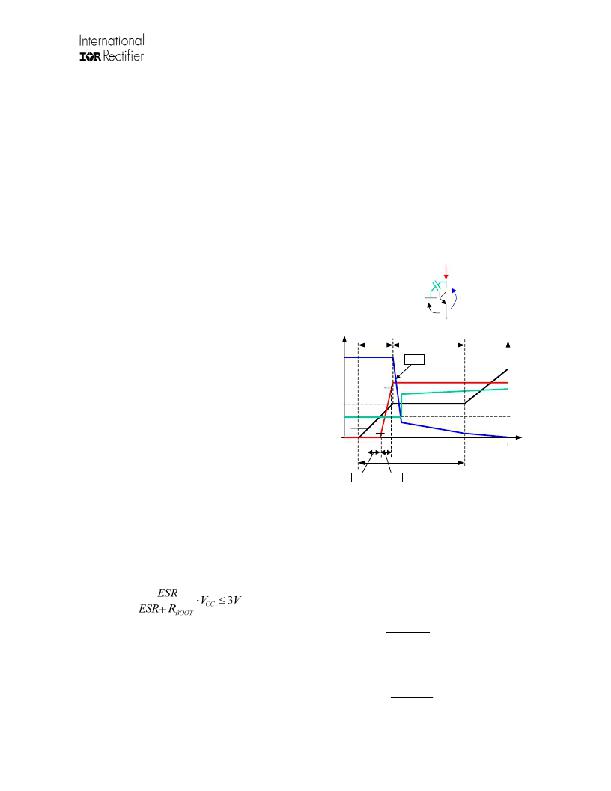
�The� example� shown� uses� IGBT� power� transistors� and�
�Figure� 20� shows� the� nomenclature� used� in� the� following�
�paragraphs.� In� addition,� V� ge*� indicates� the� plateau�
�voltage,� Q� gc� and� Q� ge� indicate� the� gate� to� collector� and�
�gate� to� emitter� charge� respectively.�
�V� BS� =� V� CC� ?� V� F�
�C� RES�
�I� C�
�I� LOAD� >� 0� A;� the� load� current� flows� through� the�
�freewheeling� diode�
�V� GE�
�V� BS� =� V� CC� ?� V� F� +� V� FP�
�t� 1� ,Q� GE�
�V� CE�
�t� 2� ,Q� GC�
�dV/dt�
�In� this� case� we� have� the� highest� value� for� V� BS� .� Turning�
�on� the� high� side� IGBT,� I� LOAD� flows� into� it� and� V� S� is�
�pulled� up.� To� minimize� the� risk� of� undervoltage,� the�
�bootstrap� capacitor� should� be� sized� according� to� the�
�I� LOAD� <� 0� A� case.�
�Bootstrap� Resistor:� A� resistor� (R� boot� )� is� placed� in� series�
�V� ge� *�
�10%�
�90%�
�10%�
�C� RES�
�I� C�
�V� GE�
�C� RESon�
�C� RESoff�
�with� the� bootstrap� diode� (see� Fig.� 19)� in� order� to� limit�
�the� current� when� the� bootstrap� capacitor� is� initially�
�t,Q�
�charged.� We� suggest� not� exceeding� 10�
�to� avoid�
�increasing� the� V� BS� time-constant.� The� minimum� on� time�
�t� SW�
�for� charging� the� bootstrap� capacitor� or� for� refreshing� its�
�charge� must� be� verified� against� this� time-constant.�
�t� Don�
�t� R�
�Bootstrap� Capacitor:� For� high� t� HON� designs� where� an�
�electrolytic� capacitor� is� used,� its� ESR� must� be�
�considered.� This� parasitic� resistance� forms� a� voltage�
�divider� with� R� boot� ,� which� generats� a� voltage� step� on� V� BS�
�at� the� first� charge� of� bootstrap� capacitor.� The� voltage�
�step� and� the� related� speed� (dV� BS� /dt)� should� be� limited.�
�As� a� general� rule,� ESR� should� meet� the� following�
�constraint.�
�Figure� 20:� Nomenclature�
�2.5� Sizing� The� Turn-On� Gate� Resistor�
�Switching-Time:� For� the� matters� of� the� calculation�
�included� hereafter,� the� switching� time� t� sw� is� defined�
�as� the� time� spent� to� reach� the� end� of� the� plateau�
�voltage� (a� total� Q� gc� +� Q� ge� has� been� provided� to� the�
�IGBT� gate).� To� obtain� the� desired� switching� time� the�
�gate� resistance� can� be� sized� starting� from� Q� ge� and�
�Q� gc� ,� Vcc� ,� V� ge*� (see� Fig.� 21):�
�A� parallel� combination� of� a� small� ceramic� capacitor� and�
�a� large� electrolytic� capacitor� is� normally� the� best�
�compromise,� the� first� capacitor� posses� a� fast� time�
�constant� and� limits� the� dV� BS� /dt� by� reducing� the�
�equivalent� resistance.� The� second� capacitor� provides� a�
�large� capacitance� to� maintain� the� V� BS� voltage� drop�
�and�
�I� avg� =�
�Q� gc� +� Q� ge�
�t� sw�
�within� the� desired� ?� V� BS� .�
�Bootstrap� Diode:� The� diode� must� have� a� BV� >� 600� V� or�
�1200� V� and� a� fast� recovery� time� (t� rr� <� 100� ns)� to�
�www.irf.com�
�18�
�R� TOT� =�
�Vcc� ?� V� ge� *�
�I� avg�
�?� 2009� International� Rectifier�
�相关PDF资料 |
PDF描述 |
|---|---|
| IR2235JPBF | IC DRIVER BRIDGE 3PHASE 44PLCC |
| IR2301PBF | IC DRIVER HIGH/LOW SIDE 8DIP |
| IR2302PBF | IC DRIVER HALF BRIDGE 8DIP |
| IR2304SPBF | IC DRIVER HALF BRIDGE 8-SOIC |
| IR2308SPBF | IC DRIVER HALF BRIDGE HV 8SOIC |
相关代理商/技术参数 |
参数描述 |
|---|---|
| IR22141SSPBF | 制造商:International Rectifier 功能描述:Driver IC |
| IR22141SSTRPBF | 功能描述:功率驱动器IC Hlf Brdg Drvr IC for Pwr Swtch App RoHS:否 制造商:Micrel 产品:MOSFET Gate Drivers 类型:Low Cost High or Low Side MOSFET Driver 上升时间: 下降时间: 电源电压-最大:30 V 电源电压-最小:2.75 V 电源电流: 最大功率耗散: 最大工作温度:+ 85 C 安装风格:SMD/SMT 封装 / 箱体:SOIC-8 封装:Tube |
| IR2214SS | 功能描述:IC DRIVER HALF BRIDGE SGL 24SSOP RoHS:否 类别:集成电路 (IC) >> PMIC - MOSFET,电桥驱动器 - 外部开关 系列:- 标准包装:50 系列:- 配置:高端 输入类型:非反相 延迟时间:200ns 电流 - 峰:250mA 配置数:1 输出数:1 高端电压 - 最大(自引导启动):600V 电源电压:12 V ~ 20 V 工作温度:-40°C ~ 125°C 安装类型:通孔 封装/外壳:8-DIP(0.300",7.62mm) 供应商设备封装:8-DIP 包装:管件 其它名称:*IR2127 |
| IR2214SSPBF | 功能描述:功率驱动器IC 1200V HALF BRDG DRVR IC RoHS:否 制造商:Micrel 产品:MOSFET Gate Drivers 类型:Low Cost High or Low Side MOSFET Driver 上升时间: 下降时间: 电源电压-最大:30 V 电源电压-最小:2.75 V 电源电流: 最大功率耗散: 最大工作温度:+ 85 C 安装风格:SMD/SMT 封装 / 箱体:SOIC-8 封装:Tube |
| IR2214SSPBF | 制造商:International Rectifier 功能描述:Driver IC |
发布紧急采购,3分钟左右您将得到回复。