- 您现在的位置:买卖IC网 > PDF目录16601 > ISL6271ACR (Intersil)IC REG PMIC 1BUCK 2LDO 20-QFN PDF资料下载
参数资料
| 型号: | ISL6271ACR |
| 厂商: | Intersil |
| 文件页数: | 14/16页 |
| 文件大小: | 0K |
| 描述: | IC REG PMIC 1BUCK 2LDO 20-QFN |
| 标准包装: | 75 |
| 应用: | 处理器 |
| 电流 - 电源: | 380µA |
| 电源电压: | 2.76 V ~ 5.5 V |
| 工作温度: | -25°C ~ 85°C |
| 安装类型: | 表面贴装 |
| 封装/外壳: | 20-VFQFN 裸露焊盘 |
| 供应商设备封装: | 20-QFN 裸露焊盘(4x4) |
| 包装: | 管件 |
�� �
�
�ISL6271A�
�Measured� Core� Voltage� Conversion� Efficiency�
�The� actual� efficiency� of� the� ISL6271A� switching� regulator� is�
�illustrated� in� Figure� 3� from� 10mA� to� 800mA.� The� curves� were�
�TOTAL� POWER� SOLUTION�
�(INTEL� XScale� PROCESSOR)�
�SINGLE�
�taken� at� room� temperature� using� the� ISL6271A� evaluation�
�board.� The� output� inductor� used� is� an� ultralow� profile,�
�drumcore� device� with� a� DCR� of� 100m� ?� .�
�10mV� RIPPLE�
�IN� DCM�
�CCM�
�RIPPLE�
�EL7536�
�3.3V�
�OUTPUT�
�REGULATOR�
�EN�
�BATT�
�TO�
�3V LDO�
�VCC_LCD�
�VCC_MEM�
�VCC_IO�
�VCC_BB�
�VCC_USB�
�VCC_BATT�
�MOS�
�SWITCH�
�INTEL�
�Xscale�
�μP�
�VCC_USIM�
�nVDD_FLT�
�nBatt_FLT�
�CELL�
�VCC_CORE� ISL6271A� LI-Io� n�
�VCC_SRAM� PMIC�
�VCC_PLL�
�I� 2� C_SDA�
�I� 2� C_SCL� EN�
�PWR_EN�
�SYS_EN�
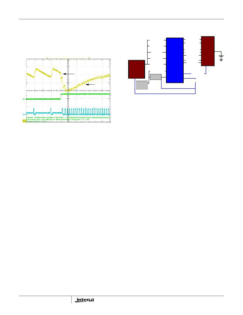
�FIGURE� 25.� XSCALE� POWER� DOMAINS�
�Design� Notes�
���FIGURE� 24.� DCM� TO� CCM� MODE� TRANSITION�
�Thermal� Management�
�Although� the� ISL6271A� is� characteristically� a� low� heat�
�generator,� it� will� generate� some� heat� as� a� result� of� the�
�inefficiencies� in� power� conversion.� The� worst-case� internal�
�power� dissipation� should� be� less� than� 250mW,� translating�
�into� a� 11°C� rise� in� junction� temperature� above� ambient.� If� the�
�temperature� of� the� chip� does� exceed� 150°� ±10°C� as� a� result�
�of� a� high� ambient� temperature,� the� controller� will� disable� the�
�outputs� until� the� temperature� decreases� by� 45°C.�
�Powering� Intel� XScale� Processors�
�Intel� identifies� ten� power� domains� required� for� powering�
�XScale� processors.� Of� these� ten� power� domains� or� voltages,�
�many� may� be� strapped� together� as� in� Figure� 25� and� supplied�
�by� a� single� regulator.� These� voltages� however� must� be�
�applied� systematically� to� the� processor� and� two� pins,�
�SYS_EN� and� PWR_EN� facilitate� this� power� sequence.� The�
�PWR_EN� pin� is� dedicated� to� enabling� the� CORE,� PLL� and�
�SRAM� power� domains� and� should� be� connected� to� the�
�ISL6271A� enable� pin.� The� SYS_EN� pin� is� responsible� for�
�enabling� the� system� regulator.� Figure� 25� illustrates� one�
�possible� configuration� using� the� Intersil� EL7536� to� power� five�
�of� the� 10� domains.�
�NOTE:� Intel� warns� that� an� improper� power� sequence� can� damage�
�the� processor.� Refer� to� the� appropriate� Intel� applications� material� to�
�ensure� proper� voltage� sequencing.�
�14�
�1.� Do� not� leave� pins� VID2(5)� or� pin� VID3(6)� floating� when�
�using� the� I� 2� C� bus.� Tie� these� pins� to� GND� (16).�
�2.� Make� sure� that� load� current� on� VOUT� returns� to� the� pin� 7�
�(PGND).� Pin� 16� (GND)� functions� as� a� quiet� return� for� the�
�LVCC� loads.� Tie� Pin� 16� to� Pin� 7� at� a� single� point� as� in�
�Figure� 19.�
�3.� Select� the� output� capacitor� for� VSRAM� and� VPLL� as�
�follows:� 2.2μF<C8,� C5<4.7μF,� X5R.�
�4.� BFLT#� is� internally� pulled� up� to� BBAT.� Do� not� pullup� to�
�any� other� external� voltage.�
�5.� The� I� 2� C� pull-up� resistors� will� affect� standby� leakage�
�power.� A� typical� value� to� accommodate� the� I� 2� C� bus� slew�
�rate� requirements� in� “Standard� Mode”� is� 5K.�
�6.� Set� the� soft-start� capacitor� to� 10nF� to� implement� a�
�1mV/μs� slew� rate� of� the� output� voltage� at� startup.� For�
�max� slew� rate,� use� 6.8nF� soft-start� capacitor.�
�7.� Tie� PGOOD� to� the� XScale� nVDD_fault� pin.�
�8.� Tie� the� BFLT#� pin� to� the� XScale� nBatt_fault� pin.� The�
�BFLT#� pin� is� pulled� up� internally� to� BBAT.� A� valid� BFLT#�
�state� under� all� conditions� can� be� achieve� by� connecting�
�BBAT� to� the� system� BACK-UP� battery.� Otherwise,�
�consider� the� system� start-up/shut-down� voltage� timing� to�
�determine� what� system� voltage� that� BBAT� can� be� tied� to�
�that� will� ensure� the� correct� BFLT#� operation.� Current�
�drain� on� BBAT� is� much� less� than� 1μA.�
�9.� It� is� a� good� design� practice� to� isolate� PVCC� from� VCC�
�with� a� low� pass� filter� (LPF)� made� up� of� a� 10� ?� resistor� and�
�0.1μF� ceramic� capacitor.� Ensure� that� VCC� is� kept� within�
�0.3V� of� PVCC� to� avoid� turning� on� internal� protection�
�diodes.�
�FN9171.1�
�相关PDF资料 |
PDF描述 |
|---|---|
| GEM18DRTF | CONN EDGECARD 36POS DIP .156 SLD |
| V150C28E150B2 | CONVERTER MOD DC/DC 28V 150W |
| 1-862545-7 | LEAD ASSY 16AWG SNG END 127MM |
| Q5-3X-1 1/2-01-SS25M | HEATSK DL WL Q53X 1-1/2"X25M BLK |
| VI-B3P-EX | CONVERTER MOD DC/DC 13.8V 75W |
相关代理商/技术参数 |
参数描述 |
|---|---|
| ISL6271ACR-T | 功能描述:IC PMIC XSCALE PROCESSOR 20-QFN RoHS:否 类别:集成电路 (IC) >> PMIC - 电源管理 - 专用 系列:- 应用说明:Ultrasound Imaging Systems Application Note 产品培训模块:Lead (SnPb) Finish for COTS Obsolescence Mitigation Program 标准包装:37 系列:- 应用:医疗用超声波成像,声纳 电流 - 电源:- 电源电压:2.37 V ~ 6 V 工作温度:0°C ~ 70°C 安装类型:表面贴装 封装/外壳:56-WFQFN 裸露焊盘 供应商设备封装:56-TQFN-EP(8x8) 包装:管件 |
| ISL6271ACRZ | 功能描述:直流/直流开关调节器 LD PLL & SRAMG FOR I NTEL PROCESSORS IBM RoHS:否 制造商:International Rectifier 最大输入电压:21 V 开关频率:1.5 MHz 输出电压:0.5 V to 0.86 V 输出电流:4 A 输出端数量: 最大工作温度: 安装风格:SMD/SMT 封装 / 箱体:PQFN 4 x 5 |
| ISL6271ACRZ-T | 功能描述:直流/直流开关调节器 LD PLL & SRAMG FOR I NTEL PROCESSORS IBM RoHS:否 制造商:International Rectifier 最大输入电压:21 V 开关频率:1.5 MHz 输出电压:0.5 V to 0.86 V 输出电流:4 A 输出端数量: 最大工作温度: 安装风格:SMD/SMT 封装 / 箱体:PQFN 4 x 5 |
| ISL6271AEVAL1 | 功能描述:EVALUATION BOARD FOR ISL6271A RoHS:否 类别:编程器,开发系统 >> 评估板 - DC/DC 与 AC/DC(离线)SMPS 系列:- 产品培训模块:Obsolescence Mitigation Program 标准包装:1 系列:True Shutdown™ 主要目的:DC/DC,步升 输出及类型:1,非隔离 功率 - 输出:- 输出电压:- 电流 - 输出:1A 输入电压:2.5 V ~ 5.5 V 稳压器拓扑结构:升压 频率 - 开关:3MHz 板类型:完全填充 已供物品:板 已用 IC / 零件:MAX8969 |
| ISL6271CR | 制造商:Rochester Electronics LLC 功能描述:PLL & SRAM REGULATOR FOR INTEL PROCESSORS - Bulk 制造商:Intersil Corporation 功能描述: |
发布紧急采购,3分钟左右您将得到回复。