参数资料
| 型号: | ISL6329IRZ-T |
| 厂商: | Intersil |
| 文件页数: | 33/38页 |
| 文件大小: | 0K |
| 描述: | IC CTRLR PWM SYNC BUCK DL 60QFN |
| 标准包装: | 4,000 |
| 应用: | 控制器,AMD SVI |
| 输入电压: | 5 V ~ 12 V |
| 输出数: | 2 |
| 输出电压: | 0.0125 V ~ 1.55 V |
| 工作温度: | -40°C ~ 85°C |
| 安装类型: | * |
| 封装/外壳: | * |
| 供应商设备封装: | * |
| 包装: | * |
第1页第2页第3页第4页第5页第6页第7页第8页第9页第10页第11页第12页第13页第14页第15页第16页第17页第18页第19页第20页第21页第22页第23页第24页第25页第26页第27页第28页第29页第30页第31页第32页当前第33页第34页第35页第36页第37页第38页
�� �
�
�ISL6329�
�Most� capacitor� solutions� rely� on� a� mixture� of� high� frequency�
�capacitors� with� relatively� low� capacitance� in� combination� with�
�bulk� capacitors� having� high� capacitance� but� limited�
�high-frequency� performance.� Minimizing� the� ESL� of� the�
�high-frequency� capacitors� allows� them� to� support� the� output�
�voltage� as� the� current� increases.� Minimizing� the� ESR� of� the� bulk�
�capacitors� allows� them� to� supply� the� increased� current� with� less�
�output� voltage� deviation.�
�The� ESR� of� the� bulk� capacitors� also� creates� the� majority� of� the�
�output-voltage� ripple.� As� the� bulk� capacitors� sink� and� source� the�
�inductor� AC� ripple� current� (see� “Interleaving”� on� page� 12� and�
�Equation� 3),� a� voltage� develops� across� the� bulk� capacitor� ESR�
�1k�
�100�
�equal� to� I� C,PP� (ESR).� Thus,� once� the� output� capacitors� are�
�selected,� the� maximum� allowable� ripple� voltage,� V� PP(MAX)� ,�
�determines� the� lower� limit� on� the� inductance.�
�10�
�10k�
�100k� 1M�
�SWITCHING� FREQUENCY� (Hz)�
�10M�
�IN� –� N� ?� V� OUT� ?� V� OUT�
�?� V� ?�
�L� ≥� ESR� ?� --------------------------------------------------------------------�
�?� ?�
�f� S� ?� V� IN� ?� V� PP� (� MAX� )�
�(EQ.� 40)�
�FIGURE� 25.� R� T� vs� SWITCHING� FREQUENCY�
�Input� Capacitor� Selection�
�Since� the� capacitors� are� supplying� a� decreasing� portion� of� the�
�load� current� while� the� regulator� recovers� from� the� transient,� the�
�capacitor� voltage� becomes� slightly� depleted.� The� output�
�inductors� must� be� capable� of� assuming� the� entire� load� current�
�before� the� output� voltage� decreases� more� than� Δ� V� MAX� .� This�
�places� an� upper� limit� on� inductance.�
�Equation� 41� gives� the� upper� limit� on� L� for� the� cases� when� the�
�trailing� edge� of� the� current� transient� causes� a� greater�
�output-voltage� deviation� than� the� leading� edge.� Equation� 42�
�addresses� the� leading� edge.� Normally,� the� trailing� edge� dictates�
�the� selection� of� L� because� duty� cycles� are� usually� less� than� 50%.�
�Nevertheless,� both� inequalities� should� be� evaluated,� and� L�
�should� be� selected� based� on� the� lower� of� the� two� results.� In� each�
�equation,� L� is� the� per-channel� inductance,� C� is� the� total� output�
�capacitance,� and� N� is� the� number� of� active� channels.�
�The� input� capacitors� are� responsible� for� sourcing� the� AC�
�component� of� the� input� current� flowing� into� the� upper� MOSFETs.�
�Their� RMS� current� capacity� must� be� sufficient� to� handle� the� AC�
�component� of� the� current� drawn� by� the� upper� MOSFETs� which� is�
�related� to� duty� cycle� and� the� number� of� active� phases.�
�0.3�
�I� L,PP� =� 0� I� L,PP� =� 0.5� I� O�
�I� L,PP� =� 0.25� I� O� I� L,PP� =� 0.75� I� O�
�0.2�
�0.1�
�L� ≤� ---------------------------------� ?� Δ� V� MAX� –� (� Δ� I� ?� ESR� )�
�2� ?� N� ?� C� ?� V� O�
�(� Δ� I� )� 2�
�(EQ.� 41)�
�L� ≤� -----------------------------� ?� Δ� V� MAX� –� (� Δ� I� ?� ESR� )� ?� ?� V� IN� –� V� O� ?�
�(� Δ� I� )� 2�
�1.25� ?� N� ?� C�
�?� ?�
�(EQ.� 42)�
�0�
�0�
�0.2�
�0.4�
�0.6�
�0.8�
�1.0�
�DUTY� CYCLE� (V� O/� V� IN� )�
�Switching� Frequency�
�There� are� a� number� of� variables� to� consider� when� choosing� the�
�switching� frequency,� as� there� are� considerable� effects� on� the�
�upper� MOSFET� loss� calculation.� These� effects� are� outlined� in�
��switching� frequency.� The� lower� limit� is� established� by� the�
�requirement� for� fast� transient� response� and� small� output-voltage�
�ripple� as� outlined� in� “Output� Filter� Design”� on� page� 32.� Choose�
�the� lowest� switching� frequency� that� allows� the� regulator� to� meet�
�the� transient-response� requirements.�
�Switching� frequency� is� determined� by� the� selection� of� the�
�frequency-setting� resistor,� R� T� .� Figure� 25� and� Equation� 43� are�
�provided� to� assist� in� selecting� the� correct� value� for� R� T� .�
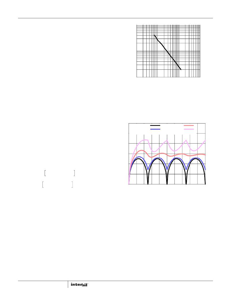
�FIGURE� 26.� NORMALIZED� INPUT-CAPACITOR� RMS� CURRENT� vs� DUTY�
�CYCLE� FOR� 4-PHASE� CONVERTER�
�For� a� four-phase� design,� use� Figure� 26� to� determine� the� input-�
�capacitor� RMS� current� requirement� set� by� the� duty� cycle,� maximum�
�sustained� output� current� (I� O� ),� and� the� ratio� of� the� peak-to-peak�
�inductor� current� (I� L,PP� )� to� I� O� .� Select� a� bulk� capacitor� with� a� ripple�
�current� rating� which� will� minimize� the� total� number� of� input�
�capacitors� required� to� support� the� RMS� current� calculated.�
�The� voltage� rating� of� the� capacitors� should� also� be� at� least� 1.25�
�times� greater� than� the� maximum� input� voltage.� Figures� 27� and� 28�
�provide� the� same� input� RMS� current� information� for� three-phase�
�and� two-phase� designs� respectively.� Use� the� same� approach� for�
�selecting� the� bulk� capacitor� type� and� number.�
�R� T� =� 10�
�[� 10.61� –� (� 1.035� ?� log� (� f� S� )� )� ]�
�33�
�(EQ.� 43)�
�FN7800.0�
�April� 19,� 2011�
�相关PDF资料 |
PDF描述 |
|---|---|
| ISL6333IRZ | IC CTRLR PWM 3PHASE BUCK 48-QFN |
| ISL6334AIRZR5368 | IC CTRLR PWM 4PHASE BUCK 40QFN |
| ISL6334BIRZ-T | IC CTRLR PWM SYNC BUCK 40-QFN |
| ISL6334CRZ | IC CTRLR PWM 4PHASE BUCK 40-QFN |
| ISL6334DIRZ | IC CTRLR PWM 4PHASE VR11.1 40QFN |
相关代理商/技术参数 |
参数描述 |
|---|---|
| ISL6333ACRZ | 功能描述:IC CTRLR PWM 3PHASE BUCK 48-QFN RoHS:是 类别:集成电路 (IC) >> PMIC - 稳压器 - 专用型 系列:- 标准包装:43 系列:- 应用:控制器,Intel VR11 输入电压:5 V ~ 12 V 输出数:1 输出电压:0.5 V ~ 1.6 V 工作温度:-40°C ~ 85°C 安装类型:表面贴装 封装/外壳:48-VFQFN 裸露焊盘 供应商设备封装:48-QFN(7x7) 包装:管件 |
| ISL6333ACRZ-T | 功能描述:IC CTRLR PWM 3PHASE BUCK 48-QFN RoHS:是 类别:集成电路 (IC) >> PMIC - 稳压器 - 专用型 系列:- 标准包装:43 系列:- 应用:控制器,Intel VR11 输入电压:5 V ~ 12 V 输出数:1 输出电压:0.5 V ~ 1.6 V 工作温度:-40°C ~ 85°C 安装类型:表面贴装 封装/外壳:48-VFQFN 裸露焊盘 供应商设备封装:48-QFN(7x7) 包装:管件 |
| ISL6333AEVAL1Z | 制造商:Intersil Corporation 功能描述: |
| ISL6333AIRZ | 功能描述:IC CTRLR PWM 3PHASE BUCK 48-QFN RoHS:是 类别:集成电路 (IC) >> PMIC - 稳压器 - 专用型 系列:- 标准包装:2,000 系列:- 应用:控制器,DSP 输入电压:4.5 V ~ 25 V 输出数:2 输出电压:最低可调至 1.2V 工作温度:-40°C ~ 85°C 安装类型:表面贴装 封装/外壳:30-TFSOP(0.173",4.40mm 宽) 供应商设备封装:30-TSSOP 包装:带卷 (TR) |
| ISL6333AIRZ-T | 功能描述:IC CTRLR PWM 3PHASE BUCK 48-QFN RoHS:是 类别:集成电路 (IC) >> PMIC - 稳压器 - 专用型 系列:- 标准包装:43 系列:- 应用:控制器,Intel VR11 输入电压:5 V ~ 12 V 输出数:1 输出电压:0.5 V ~ 1.6 V 工作温度:-40°C ~ 85°C 安装类型:表面贴装 封装/外壳:48-VFQFN 裸露焊盘 供应商设备封装:48-QFN(7x7) 包装:管件 |
发布紧急采购,3分钟左右您将得到回复。