参数资料
| 型号: | ISL6334ACRZ-TR5368 |
| 厂商: | Intersil |
| 文件页数: | 14/31页 |
| 文件大小: | 0K |
| 描述: | IC CTRLR PWM 4PHASE BUCK 40QFN |
| 标准包装: | 4,000 |
| 应用: | 控制器,Intel VR11.1 |
| 输入电压: | 3 V ~ 12 V |
| 输出数: | 1 |
| 输出电压: | 0.5 V ~ 1.6 V |
| 工作温度: | 0°C ~ 70°C |
| 安装类型: | 表面贴装 |
| 封装/外壳: | 40-VFQFN 裸露焊盘 |
| 供应商设备封装: | 40-QFN(6x6) |
| 包装: | 带卷 (TR) |
第1页第2页第3页第4页第5页第6页第7页第8页第9页第10页第11页第12页第13页当前第14页第15页第16页第17页第18页第19页第20页第21页第22页第23页第24页第25页第26页第27页第28页第29页第30页第31页
�� �
�
�ISL6334AR5368�
�pin� and� ground.� The� PWM� signals� command� the� MOSFET�
�driver� to� turn� on/off� the� channel� MOSFETs.�
�For� 4-channel� operation,� the� channel� firing� order� is� 1-2-3-4:�
�PWM3� pulse� happens� 1/4� of� a� cycle� after� PWM4,� PWM2�
�output� follows� another� 1/4� of� a� cycle� after� PWM3,� and�
�PWM1� delays� another� 1/4� of� a� cycle� after� PWM2.� For�
�3-channel� operation,� the� channel� firing� order� is� 1-2-3.�
�Connecting� PWM4� to� VCC� selects� three� channel� operation�
�and� the� pulse� times� are� spaced� in� 1/3� cycle� increments.� If�
�level� set� by� the� controller� IC.� Therefore,� the� controller� ’s�
�PWM� outputs� are� directly� compatible� with� Intersil� drivers� that�
�require� 5V� PWM� signal� amplitudes.� Drivers� requiring� 3.3V�
�PWM� signal� amplitudes� are� generally� incompatible.�
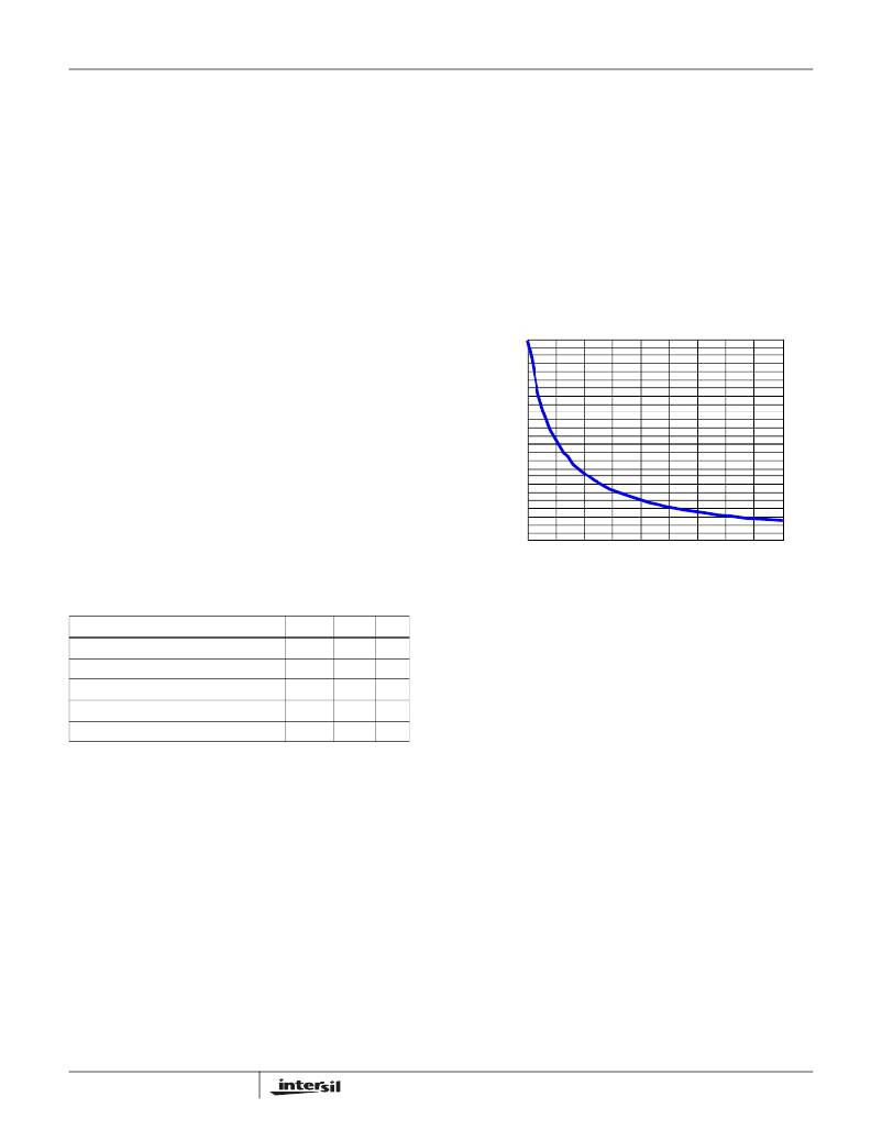
�Switching� Frequency�
�Switching� frequency� is� determined� by� the� selection� of� the�
�frequency-setting� resistor,� R� T� ,� which� is� connected� from� FS�
�pin� to� GND� or� VCC.� Equation� 3� and� Figure� 3� are� provided� to�
�assist� in� selecting� the� correct� resistor� value.�
�R� T� =� --------------------------�
�PWM3� is� connected� to� VCC,� two� channel� operation� is�
�selected� and� the� PWM2� pulse� happens� 1/2� of� a� cycle� after�
�PWM1� pulse.� If� PWM2� is� connected� to� VCC,� only� Channel� 1�
�operation� is� selected.� In� addition,� tie� PSI#� to� GND� to�
�configure� for� single� or� 2-phase� operation� with� diode�
�10�
�2.5X10�
�F� SW�
�where� F� SW� is� the� switching� frequency� of� each� phase.�
�250�
�(EQ.� 3)�
�emulation� on� remaining� channel(s),� Channel� 1� or� Channels�
�1� and� 3.�
�200�
�When� PSI#� is� asserted� low,� indicating� the� low� power� mode�
�operation� of� the� processor,� the� controller� drops� the� number� of�
�active� phases� according� to� the� logic� on� Table� 1� for� highlight�
�load� efficiency� performance.� SS� and� FS� pins� are� used� to�
�program� the� controller� in� operation� of� non-coupled,� 2-phase�
�coupled,� or� (n-x)-Phase� coupled� inductors.� Different� cases� yield�
�different� PWM� output� behaviors� on� both� dropped� phase(s)� and�
�remained� phase(s)� as� PSI#� is� asserted� and� de-asserted.� A� high�
�150�
�100�
�50�
�PSI#� input� signal� pulls� the� controller� back� to� normal� CCM� PWM�
�operation� to� sustain� an� immediate� heavy� transient� load� and�
�high� efficiency.� Note� that� “n-x”� means� n-x� phase� coupled� and� x�
�phase(s)� are� uncoupled.�
�TABLE� 1.� PSI#� OPERATION� DECODING�
�0�
�100k� 200k� 300k� 400k� 500k� 600k� 700k� 800k� 900k�
�SWITCHING� FREQUENCY� (Hz)�
�FIGURE� 3.� SWITCHING� FREQUENCY� vs� RT�
�Current� Sensing�
�1M�
�PSI#�
�FS�
�SS�
�The� ISL6334AR5368� senses� current� continuously� for� fast�
�Non� CI� or� (n-1)� CI� Drops� to� 1-phase�
�Non� CI� or� (n-2)� CI� Drops� to� 2-phase�
�2-phase� CI� Drops� to� 1-phase�
�2-phase� CI� Drops� to� 2-phase�
�Normal� CCM� PWM� Mode�
�0�
�0�
�0�
�0�
�1�
�0�
�0�
�1�
�1�
�x�
�0�
�1�
�0�
�1�
�x�
�response.� The� ISL6334AR5368� supports� inductor� DCR�
�sensing,� or� resistive� sensing� techniques.� The� associated�
�channel� current� sense� amplifier� uses� the� ISEN� inputs� to�
�reproduce� a� signal� proportional� to� the� inductor� current,� I� L� .�
�The� sense� current,� I� SEN� ,� is� proportional� to� the� inductor�
�current.� The� sensed� current� is� used� for� current� balance,�
�The� dropped� PWM� is� forced� low� for� 200ns� (uncoupled� case)�
�or� until� falling� edge� of� coupled� PWM� (coupled� case)� then�
�pulled� to� VCC/2,� while� the� remained� PWM(s)� sends� out� a�
�special� 3-level� PWM� protocol� that� the� dedicated� VR11.1�
�drivers� can� decode� and� then� enter� diode� emulation� mode�
�with� gate� drive� voltage� optimization.�
�The� ISL6334AR5368� only� generates� 2-level� normal� CCM�
�PWM� except� for� faults.� No� dedicated� VR11.1� driver� is� required.�
��While� the� controller� is� operational� (VCC� above� POR,�
�EN_VTT� and� EN_PWR� are� both� high,valid� VID� inputs),� it� can�
�pull� the� PWM� pins� to� ~40%� of� VCC� (~2V� for� 5V� VCC� bias)�
�during� various� stages,� such� as� soft-start� delay,� phase�
�shedding� operation,� or� fault� conditions� (OC� or� OV� events).�
�The� matching� driver� ’s� internal� PWM� resistor� divider� can�
�further� raise� the� PWM� potential,� but� not� lower� it� below� the�
�14�
�load-line� regulation,� and� overcurrent� protection.�
�The� internal� circuitry,� shown� in� Figures� 4� and� 5,� represents�
�one� channel� of� an� N-channel� converter.� This� circuitry� is�
�repeated� for� each� channel� in� the� converter,� but� may� not� be�
�active� depending� on� the� status� of� the� PWM2,� PWM3� and�
���amplifier� is� typically� 60nA;� less� than� 5k� � input� impedance� is�
�preferred� to� minimized� the� offset� error.�
�INDUCTOR� DCR� SENSING�
�An� inductor� ’s� winding� is� characteristic� of� a� distributed�
�resistance,� as� measured� by� the� DCR� (Direct� Current�
�Resistance)� parameter.� Consider� the� inductor� DCR� as� a�
�separate� lumped� quantity,� as� shown� in� Figure� 4.� The�
�channel� current� I� L� ,� flowing� through� the� inductor,� will� also�
�FN6839.2�
�September� 7,� 2010�
�相关PDF资料 |
PDF描述 |
|---|---|
| LT3015IMSE#PBF | IC REG LDO NEG ADJ 1.5A 12MSOP |
| LT3015ET#PBF | IC REG LDO NEG ADJ 1.5A 5-TO220 |
| ESM24DRMD | CONN EDGECARD 48POS .156 WW |
| GSC50DREI-S13 | CONN EDGECARD 100PS .100 EXTEND |
| EL7586ILZ-T7 | IC POWER SUPPLY TFT-LCD 20-QFN |
相关代理商/技术参数 |
参数描述 |
|---|---|
| ISL6334ACRZ-TR5453 | 制造商:Intersil Corporation 功能描述:STD. ISL6334ACRZ-T W/GOLD BOND WIRE ONLY T&R - Tape and Reel |
| ISL6334AIRZ | 功能描述:IC CTRLR PWM 4PHASE BUCK 40-QFN RoHS:是 类别:集成电路 (IC) >> PMIC - 稳压器 - 专用型 系列:- 标准包装:43 系列:- 应用:控制器,Intel VR11 输入电压:5 V ~ 12 V 输出数:1 输出电压:0.5 V ~ 1.6 V 工作温度:-40°C ~ 85°C 安装类型:表面贴装 封装/外壳:48-VFQFN 裸露焊盘 供应商设备封装:48-QFN(7x7) 包装:管件 |
| ISL6334AIRZR5368 | 功能描述:IC CTRLR PWM 4PHASE BUCK 40QFN RoHS:是 类别:集成电路 (IC) >> PMIC - 稳压器 - 专用型 系列:- 标准包装:43 系列:- 应用:控制器,Intel VR11 输入电压:5 V ~ 12 V 输出数:1 输出电压:0.5 V ~ 1.6 V 工作温度:-40°C ~ 85°C 安装类型:表面贴装 封装/外壳:48-VFQFN 裸露焊盘 供应商设备封装:48-QFN(7x7) 包装:管件 |
| ISL6334AIRZ-T | 功能描述:IC CTRLR PWM 4PHASE BUCK 40-QFN RoHS:是 类别:集成电路 (IC) >> PMIC - 稳压器 - 专用型 系列:- 标准包装:43 系列:- 应用:控制器,Intel VR11 输入电压:5 V ~ 12 V 输出数:1 输出电压:0.5 V ~ 1.6 V 工作温度:-40°C ~ 85°C 安装类型:表面贴装 封装/外壳:48-VFQFN 裸露焊盘 供应商设备封装:48-QFN(7x7) 包装:管件 |
| ISL6334AIRZ-TR5368 | 功能描述:IC CTRLR PWM 4PHASE BUCK 40QFN RoHS:是 类别:集成电路 (IC) >> PMIC - 稳压器 - 专用型 系列:- 标准包装:43 系列:- 应用:控制器,Intel VR11 输入电压:5 V ~ 12 V 输出数:1 输出电压:0.5 V ~ 1.6 V 工作温度:-40°C ~ 85°C 安装类型:表面贴装 封装/外壳:48-VFQFN 裸露焊盘 供应商设备封装:48-QFN(7x7) 包装:管件 |
发布紧急采购,3分钟左右您将得到回复。