参数资料
| 型号: | ISL6336AIRZ |
| 厂商: | Intersil |
| 文件页数: | 27/31页 |
| 文件大小: | 0K |
| 描述: | IC CTRLR PWM 6PHASE BUCK 48-QFN |
| 标准包装: | 43 |
| 应用: | 控制器,Intel VR11.1 |
| 输入电压: | 3 V ~ 12 V |
| 输出数: | 1 |
| 输出电压: | 0.5 V ~ 1.6 V |
| 工作温度: | -40°C ~ 85°C |
| 安装类型: | 表面贴装 |
| 封装/外壳: | 48-VFQFN 裸露焊盘 |
| 供应商设备封装: | 48-QFN(7x7) |
| 包装: | 管件 |
第1页第2页第3页第4页第5页第6页第7页第8页第9页第10页第11页第12页第13页第14页第15页第16页第17页第18页第19页第20页第21页第22页第23页第24页第25页第26页当前第27页第28页第29页第30页第31页
�� �
�
�ISL6336,� ISL6336A�
�C� 2� (OPTIONAL)�
�ISL6336,� ISL6336A�
�The� optional� capacitor� C� 2� ,� is� sometimes� needed� to� bypass�
�noise� away� from� the� PWM� comparator� (see� Figure� 19).� Keep�
�a� position� available� for� C� 2� ,� and� be� prepared� to� install� a� high�
�R� C�
�C� C�
�COMP�
�FB�
�frequency� capacitor� between� 22pF� and� 150pF� in� case�
�excessive� jitter� is� noted.�
�Once� selected,� the� compensation� values� in� Equation� 37�
�ensure� a� stable� converter� with� reasonable� transient�
�+�
�performance.� In� most� cases,� transient� performance� can� be�
�R� FB�
�V� DROOP�
�-�
�VDIFF�
�improved� by� making� adjustments� to� R� C� .� Slowly� increase� the�
�value� of� R� C� while� observing� the� transient� performance� on� an�
�oscilloscope� until� no� further� improvement� is� noted.� Normally,�
�C� C� will� not� need� adjustment.� Keep� the� value� of� C� C� from�
�FIGURE� 19.� COMPENSATION� CONFIGURATION� FOR�
�LOAD-LINE� REGULATED� ISL6336,� ISL6336A�
�CIRCUIT�
�The� feedback� resistor,� R� FB� ,� has� already� been� chosen� as�
�outlined� in� “Load-Line� Regulation� Resistor”� on� page� 26.�
�Select� a� target� bandwidth� for� the� compensated� system,� f� 0� .�
�The� target� bandwidth� must� be� large� enough� to� ensure�
�adequate� transient� performance,� but� generally� smaller� than�
�1/3� of� the� per-channel� switching� frequency.� The� values� of� the�
�compensation� components� depend� on� the� relationships� of� f� 0�
�to� the� L-C� pole� frequency� and� the� ESR� zero� frequency.� For�
�each� of� the� three� cases� which� follow,� there� are� a� separate�
�set� of� equations� for� the� compensation� components.�
�Equation� 37� unless� some� performance� issue� is� noted.�
�C� 1� and� R� 1� can� also� be� added� to� improve� transient�
�performance� per� the� type� III� compensation� discussion� below.�
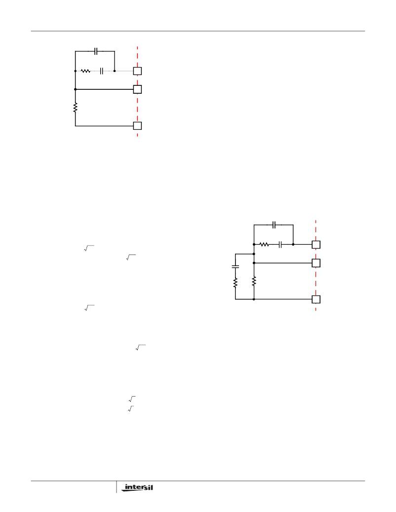
�COMPENSATION� WITHOUT� LOAD-LINE� REGULATION�
�The� non� load-line� regulated� converter� is� accurately� modeled�
�as� a� voltage-mode� regulator� with� two� poles� at� the� L-C�
�resonant� frequency� and� a� zero� at� the� ESR� frequency.� A�
�type� III� controller,� as� shown� in� Figure� 20,� provides� the�
�necessary� compensation.�
�C� 2�
�ISL6336,� ISL6336A�
�-------------------� >� f� 0�
�Case� 1:�
�1�
�2� π� LC�
�R� C�
�C� C�
�COMP�
�0.75V� IN�
�2� π� V� PP� R� FB� f� 0�
�-------------------� ≤� f� 0� <� ------------------------------�
�Case� 2:�
�2� π� f� 0� V� P-P� LC�
�R� C� =� R� FB� --------------------------------------�
�0.75V� IN�
�C� C� =� ------------------------------------�
�1� 1�
�2� π� LC� 2� π� C� (� ESR� )�
�C� 1�
�R� 1�
�R� FB�
�FB�
�VDIFF�
�0.75� V� IN�
�C� C� =� -------------------------------------------------------------�
�PP� R� FB� LC�
�(� 2� π� )� 2� f� 2� V�
�V� P-P� (� 2� π� )� 2� f� 02� LC�
�R� C� =� R� FB� ----------------------------------------------�
�0.75V� IN�
�0�
�(EQ.� 37)�
�FIGURE� 20.� COMPENSATION� CIRCUIT� FOR� ISL6336,� ISL6336A�
�BASED� CONVERTER� WITHOUT� LOAD-LINE�
�REGULATION�
�The� first� step� is� to� choose� the� desired� bandwidth,� f� 0� ,� of� the�
�compensated� system.� Choose� a� frequency� high� enough� to�
�ensure� adequate� transient� performance� but� generally� not�
�f� 0� >� ------------------------------�
�0.75� V� IN� (� ESR� )�
�2� π� V� P-P� R� FB� f� 0� L�
�Case� 3:�
�1�
�2� π� C� (� ESR� )�
�2� π� f� 0� V� P-P� L�
�R� C� =� R� FB� ------------------------------------------�
�0.75V� IN� (� ESR� )� C�
�C� C� =� -------------------------------------------------�
�higher� than� 1/3� of� the� switching� frequency.� The� type-III�
�compensator� has� an� extra� high-frequency� pole,� f� HF� .� This�
�pole� can� be� used� for� added� noise� rejection� or� to� ensure�
�adequate� attenuation� at� the� error-amplifier� high-order� pole�
�and� zero� frequencies.� A� good� general� rule� is� to� choose�
�f� HF� =� 10f� 0� ,� but� it� can� be� higher� if� desired.� Choosing� f� HF� to� be�
�lower� than� 10f� 0� can� cause� problems� with� too� much� phase�
�shift� below� the� system� bandwidth.�
�In� Equation� 37,� L� is� the� per-channel� filter� inductance� divided�
�by� the� number� of� active� channels;� C� is� the� sum� total� of� all�
�output� capacitors;� ESR� is� the� equivalent-series� resistance� of�
�the� bulk� output-filter� capacitance;� and� V� PP� is� the� peak-to-�
�peak� sawtooth� signal� amplitude� as� described� in� the�
��27�
�In� the� solutions� to� the� compensation� equations,� there� is� a�
�single� degree� of� freedom.� For� the� solutions� presented� in�
�Equation� 38,� R� FB� is� selected� arbitrarily.� The� remaining�
�compensation� components� are� then� selected� according� to�
�Equation� 38.�
�FN6504.1�
�May� 28,� 2009�
�相关PDF资料 |
PDF描述 |
|---|---|
| X40030S14I-B | IC VOLTAGE MONITOR TRPL 14-SOIC |
| ISL6336CRZ | IC CTRLR PWM 6PHASE BUCK 48-QFN |
| X40030S14I-AT1 | IC VOLTAGE MONITOR TRPL 14-SOIC |
| ASC25DREH-S13 | CONN EDGECARD 50POS .100 EXTEND |
| ASM11DSAN | CONN EDGECARD 22POS R/A .156 SLD |
相关代理商/技术参数 |
参数描述 |
|---|---|
| ISL6336AIRZ-T | 功能描述:IC CTRLR PWM 6PHASE BUCK 48-QFN RoHS:是 类别:集成电路 (IC) >> PMIC - 稳压器 - 专用型 系列:- 标准包装:43 系列:- 应用:控制器,Intel VR11 输入电压:5 V ~ 12 V 输出数:1 输出电压:0.5 V ~ 1.6 V 工作温度:-40°C ~ 85°C 安装类型:表面贴装 封装/外壳:48-VFQFN 裸露焊盘 供应商设备封装:48-QFN(7x7) 包装:管件 |
| ISL6336BCRZ | 功能描述:IC CTRLR PWM SYNC BUCK 48-QFN RoHS:是 类别:集成电路 (IC) >> PMIC - 稳压器 - 专用型 系列:- 产品培训模块:Lead (SnPb) Finish for COTS Obsolescence Mitigation Program 标准包装:2,000 系列:- 应用:电源,ICERA E400,E450 输入电压:4.1 V ~ 5.5 V 输出数:10 输出电压:可编程 工作温度:-40°C ~ 85°C 安装类型:表面贴装 封装/外壳:42-WFBGA,WLCSP 供应商设备封装:42-WLP 包装:带卷 (TR) |
| ISL6336BCRZ-T | 功能描述:IC CTRLR PWM SYNC BUCK 48-QFN RoHS:是 类别:集成电路 (IC) >> PMIC - 稳压器 - 专用型 系列:- 标准包装:43 系列:- 应用:控制器,Intel VR11 输入电压:5 V ~ 12 V 输出数:1 输出电压:0.5 V ~ 1.6 V 工作温度:-40°C ~ 85°C 安装类型:表面贴装 封装/外壳:48-VFQFN 裸露焊盘 供应商设备封装:48-QFN(7x7) 包装:管件 |
| ISL6336BIRZ | 功能描述:IC CTRLR PWM SYNC BUCK 48-QFN RoHS:是 类别:集成电路 (IC) >> PMIC - 稳压器 - 专用型 系列:- 产品培训模块:Lead (SnPb) Finish for COTS Obsolescence Mitigation Program 标准包装:2,000 系列:- 应用:电源,ICERA E400,E450 输入电压:4.1 V ~ 5.5 V 输出数:10 输出电压:可编程 工作温度:-40°C ~ 85°C 安装类型:表面贴装 封装/外壳:42-WFBGA,WLCSP 供应商设备封装:42-WLP 包装:带卷 (TR) |
| ISL6336BIRZ-T | 功能描述:IC CTRLR PWM SYNC BUCK 48-QFN RoHS:是 类别:集成电路 (IC) >> PMIC - 稳压器 - 专用型 系列:- 标准包装:43 系列:- 应用:控制器,Intel VR11 输入电压:5 V ~ 12 V 输出数:1 输出电压:0.5 V ~ 1.6 V 工作温度:-40°C ~ 85°C 安装类型:表面贴装 封装/外壳:48-VFQFN 裸露焊盘 供应商设备封装:48-QFN(7x7) 包装:管件 |
发布紧急采购,3分钟左右您将得到回复。